Known Issue/Feature request tracking thread

As developers, we get to be the very first to encounter bugs and issues with hardware. What an honor! Let’s keep track of them here in this thread. Feel free to reply with anything you think that needs addressing, suggestions for solutions and that sort of thing. We’ll use this list as we update the design and move onto the release version. I’ll start!

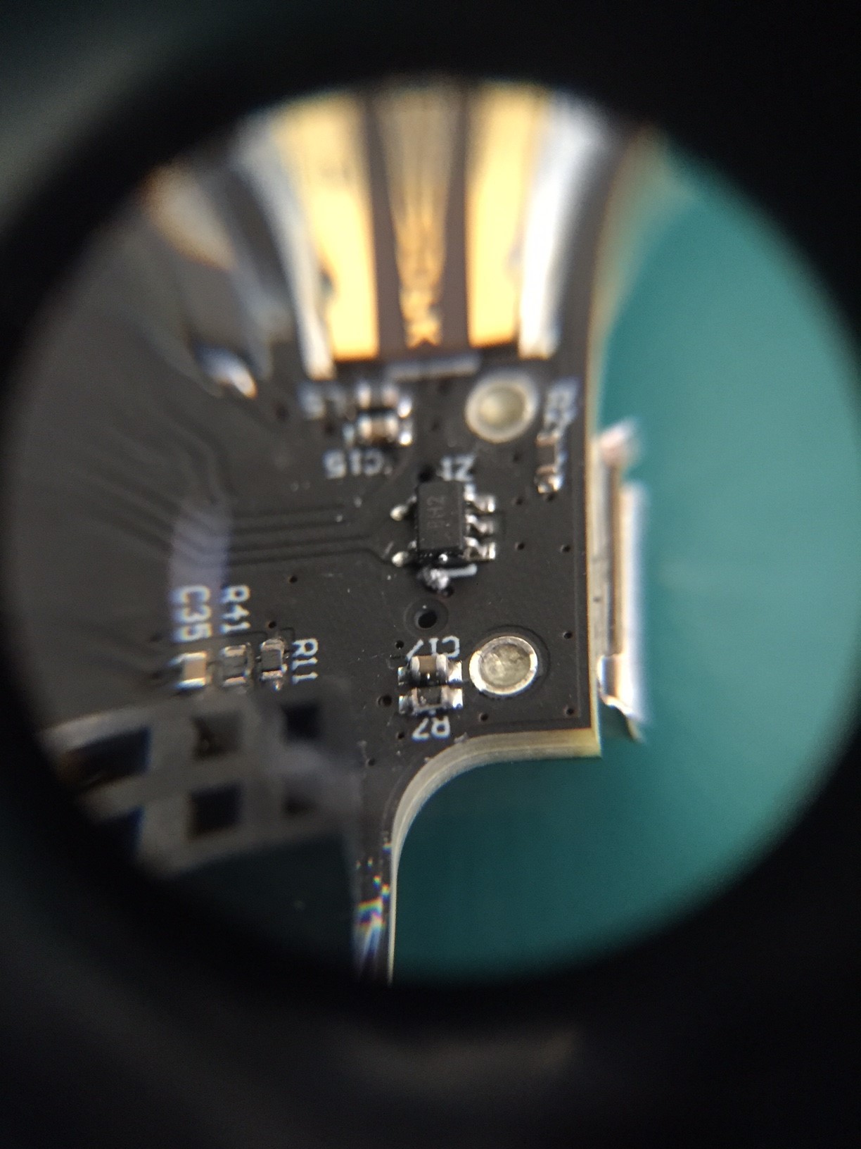
  1. USB connector: poor quality solder connections. Symptom: wiggle the USB cable and USB connection drops intermittently. Solution: Solder it better or find a thru-hole microUSB part. USB connection can see a lot of forces. We want a robust connection here. Occurrences: 1

  2. FB1, D1 on interface board - need to check current rating to ensure it is higher than the max trip current of F1. Will use: 732-6119-1-ND instead.

  3. Feature request: add header or row of pins to processor board to break out “programming port” connections to SAM3X. Pins would be: RESET, RX, TX, 5V, ERASE, GND

  4. Replace TPS54327 with TPS54328 (same part, but higher efficiency at low loads).

  5. Change CAN transceiver rail to non-switched. (allows for wake-on-can activity).

  6. Improve 6 driver circuits - currently able to make dead short via software. Need hardware solution.

  7. Break 6 analog inputs away from outputs. Currently 6 Inputs OR Outputs, change to 6 Inputs AND Outputs.

Some solder blobs/residue left over near the USB port, specifically a big blob near “Z1”. Mine is development unit #16.

Ben

Hello all, maybe my problem is something that I just am forgetting or I would like to see if it should be added to the list. I was able to program my board once, and I just made a simple program with the led’s to understand the process of programming the board before going any further. After that, I am unable to program the Due module anymore, I am awarded “A request for the USB device descriptor failed.” in the device on Device Manager. I’m unsure if this may have been caused by me inadvertently pressing the erase button on the top, because I am not sure what is does, or if it may be a freak accident. The code is currently running so I am unsure what is really going on. What Should I do to fix this? This is also my first post so if something is amiss just let me know. Thanks.

EDIT–
I have tested this on three computers in total, using 2 different cables, all on up-to-date Windows 10, and Arduino IDE, while I was able to program on only one before this occurred.

Give this a try:

Power up M2 via USB, Press and hold “ERASE” button and then press and release “RESET” button. This should get things back to normal.

Let us know if that works.

Great, Thanks! It works! Off I go!

Not sure if I already mentioned this or not but I can think of one modification that will simplify your interface board somewhat but might require some re-engineering of the board.

I think you should add a 2 row 32 pin header prior to the ODBII connection. This header should be setup so that it is pins sticking up but could be used to mount a ribbon cable to or just put jumper blocks on.

Basically you would take the lines currently going to the ODBII port and break them putting this header at the break in a manner that if one was to put standard jumpers across the pins it would connect the two sides of the break and would be the same as having the under dash version.

The point of this is then you can get rid of the under hood version and just have this one version. The header then could be used to pass the lines out of the unit as a ribbon cable if needed but the ODBII port would still be there too.

This configuration would also allow one to connect a second ODBII port to the header and by changing some wiring you could use it to go between a scantool and the ODBII port. Or lots of flexibility one doesn’t have with the standard under dash setup.

And setting it up this way would do away needing two different versions.

I am getting same sort of issue here. I could able to program using simple sketch to blink LED. After uploading of sketch nothing happens. I tried to make my board normal by pressing ERASE+RESET release but no luck. Is it a known issue?

log for your info:


Atmel SMART device 0x285e0a60 found
Erase flash
done in 0.020 seconds

Write 24392 bytes to flash (96 pages)

[ ] 0% (0/96 pages)
[== ] 9% (9/96 pages)
[===== ] 18% (18/96 pages)
[======== ] 28% (27/96 pages)
[=========== ] 37% (36/96 pages)
[============== ] 46% (45/96 pages)
[================ ] 56% (54/96 pages)
[=================== ] 65% (63/96 pages)
[====================== ] 75% (72/96 pages)
[========================= ] 84% (81/96 pages)
[============================ ] 93% (90/96 pages)
[==============================] 100% (96/96 pages)
done in 1.904 seconds

Verify 24392 bytes of flash

[ ] 0% (0/96 pages)
[== ] 9% (9/96 pages)
[===== ] 18% (18/96 pages)
[======== ] 28% (27/96 pages)
[=========== ] 37% (36/96 pages)
[============== ] 46% (45/96 pages)
[================ ] 56% (54/96 pages)
[=================== ] 65% (63/96 pages)
[====================== ] 75% (72/96 pages)
[========================= ] 84% (81/96 pages)
[============================ ] 93% (90/96 pages)
[==============================] 100% (96/96 pages)
Verify successful
done in 1.552 seconds
Set boot flash true
CPU reset.

I have 33rd developer board.

Thanks,
jay

Sorry you are having trouble. Your log makes it look like everything is uploading correctly though.

I’ve noticed that if you do a hard ERASE via the RESET/ERASE buttons, you need to press RESET after uploading a sketch for the first time. After that, it usually automatically runs after uploading. Give that a try.

Upload a sketch and then ONLY press the RESET button.

Thank you josh. I could able to flash “fade” sketch available on your forum and see LEDs glowing.

I’d like to suggest forking https://github.com/arduino/ArduinoCore-sam so you can adjust the naming in the boards.txt. As someone who uses Arduino Due boards in other applications, having multiple entries in the board manager named identically is confusing, especially if they aren’t at the same version.

Forking the ArduinoCore-sam project would let you update the boards.txt to denote Macchina M2 as the hardware.

arduino_due_x_dbg.name=Arduino Due (Native Port)
arduino_due_x_dbg.build.usb_manufacturer="Macchina"
arduino_due_x_dbg.build.usb_product="Macchina M2 "

If I end up needing more memory for the onboard EEPROM is it as simple as desoldering the 24AA32A chip and installing one such as a 24AA1025 chip? Looks like they are the same pinout and requirements other than one is 32k and the other is 1meg.

Other than the ~$2.25 difference in price was there any other reason why the smaller unit was used?

At this point it is a non-issue but assuming I work on the OpenXC protocol and it works out but the device needs a bigger eeprom on it I am curious if there is anything else to be aware of. (Note that If I end up with a need for more room I would likely go with the 1 meg, see how it goes. Just that if I go through the trouble of increasing the size the cost really is moot.

“640k ought to be enough for anybody.”

32k < 640k…

:sweat:

( sorry, couldn’t help myself. maybe someone else will have a productive response. :slight_smile: )

EEPROM tends to be one of those weird areas where some people need none, almost everyone can get by with just a little bit, and a few people want a bunch. But, if you need to store a lot of reasonably static data you can also just plain put it into FLASH when you’re writing the sketch. The M2 has plenty of FLASH memory so chances are you can just store big tables in FLASH as you figure out PIDs and such and then users can select a bank of PIDs that correspond to their car. The selection for which bank of settings can be done in EEPROM and won’t take up but a byte or two. In this way you get the best of both worlds. EEPROM really should be used for things that absolutely must persist between flashings of the sketch. For everything and anything else there’s mastercard and const storage in FLASH.

Yes, will have to see how everything works out. Likely will be enough as is but just curious how easy it would be to add more.

I will use what I have and go from there…
With the OpenXC stuff assuming I work on that I plan to put as much into the code as possible and just store the “extra” stuff on SDcard which could be loaded into flash to be used so it is there the next time it is used. The only time it would be reloaded then would be when the M2 is connected to a different vehicle.

Hey Rod, if you do end up wanting to swap out the EEPROM, you might consider using one that this library supports so your code won’t need to change much:

Make sure pinout is the same and it should work just fine.

1 Like

The library that is mentioned for the M2 project does say that if you have more than one chip on the I2C bus it will be recognized as one contiguous block, and when i was looking at the docs for the M2 it appears the I2C bus is carried out to the external connector so if someone needed to have additional storage that might be the best bet. Maybe even have a small add on board that could have the memory on it that was preloaded with the PID’s of a bunch of vehicles or something.

Rodney

Hi all! I want to know if M2 is able to do slow init (5 baud) on K line for protocols like KWP2000 or KW1281. From datasheet of TJA1021 it seems not. Would be nice to add this feature, maybe changing the transceiver??

1 Like

Hey @minDark, M2 should be able to do KWP2000 no problem since they have the same physical layer as ISO9141. I beleive KW1281 is the same situation - someone please correct me if I am wrong.

We’ve had good luck with this library for ISO9141:

and the author has started some work on the KWP2000 code as well.

If you are able to test it, please report back your findings! Thanks!