Help wanted - how low can you go?

Let’s see how low we can make the current draw on M2! It sure would be nice to leave M2 plugged into a car and not have to worry about draining the battery.

To accomplish this, we’ll need to take advantage of several things, including the “Low Power Control” circuit found on page 4 of the interface board schematic found here.

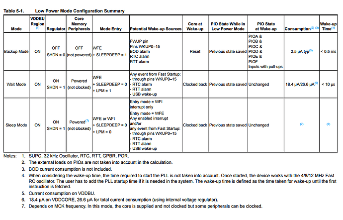
Then, we’ll want to turn off all peripherals, and put the SAM3X into a low power mode. The SAM3X offers several ways of doing this, as shown on this table found on page 27 of the datasheet:

Ideally, we’d wake up by monitoring the ADC line (PA6, or Analog IN 4) that is tied to the main +12V input. The idea is that when the voltage drops to a certain level, this assumes that the car is turned off. When that voltage raises to a certain level, we can assume the car is turned back on (Alternator is in use).

There are a few projects floating around out there we can use for reference, here are a couple:

https://forum.arduino.cc/index.php?topic=469943.0

http://wiki.wood-walker.com/doku.php/en/ww-core/power-management/conntroller

So, Let’s work together to figure this one out!

1 Like

I just tested the example code: “#1 Power saving example” found on that second link, and also added the Low power Control lines to drive “J1850 9141 ON” LOW and turn off power to a couple circuits via “+12V_SW” and “+5V_SW” rails. Here is that code:

[details=Power saving example]```cpp
#include "SamNonDuePin.h"
const int LPC = PIN_EMAC_ERX0; // LOW POWER CONTROL pin

int i = 0; //count the blinks before switching back to full speed
int delaytime = 3; //delay time varies with clock speed.

void setup() {
pmc_mck_set_prescaler(PMC_PCK_PRES_CLK_64); // master clock prescaler set to 64
pmc_switch_mainck_to_fastrc(CKGR_MOR_MOSCRCF_4_MHz);
pmc_disable_udpck(); //switch off USB clock
// This brings the 3.3 Volt power consumption from 100 mA to 19 mA
pinMode(12, OUTPUT);
pinModeNonDue(LPC, OUTPUT);
digitalWriteNonDue(LPC, LOW); // LOW = no power at +12V_SW/+5V_SW
// HIGH = power at +12V_SW/+5V_SW
}
void loop() {
// put your main code here, to run repeatedly:
digitalWrite(12, HIGH); // turn the LED on
delay(delaytime);
digitalWrite(12, LOW); // turn the LED off
delay(delaytime);
i++;
if (i > 20) { // do 20 loop runs with energy settings
// switch back to regular operating
pmc_mck_set_prescaler(PMC_PCK_PRES_CLK_2);
pmc_switch_mainck_to_xtal(PMC_OSC_XTAL);
pmc_enable_udpck(); //switch on USB clock
i = 31;
delaytime = 150;
}
}


Comparing to the simple "Blink.INO" example, M2 will draw about **100mA @12V** just to blink an LED, after running the above code, that drops to about **38mA @ 12V**. Not bad, but I know we can do better. A couple things to do still:

- put U11 (TH8056) to sleep by pulling **SWC M1** and **SWC M2** LOW.
- Make U12 (MCP2515) go to sleep over SPI (I think?)
- Put U7 and U8 (both TJA1021) to sleep by bringing their **SLP_N** LOW
- Put SAM3X into one of the 3 low power modes. 

Can anyone out there do better than 38mA @ 12V?
1 Like

Just found this example from none other than ATMEL.


http://asf.atmel.com/docs/3.19.0/sam.drivers.adc.adc_threshold_wakeup_example.arduino_due_x/html/index.html

Purpose: The adc_threshold_wakeup example demonstrates how to use ADC with threshold wakeup.

Description This example uses TIOA0 as external trigger instead of software trigger for ADC conversion. The TIOA0 is a 1ms period square wave. The rising edge during each period would trigger the ADC to start a conversion on the given channel which is connected to the potentiometer.


Anyone want to give it a try?

I gave it a try. I did pretty much all of the things you said - disabled transceivers, put the 2515 into sleep, then put the processor to sleep (essentially permanently) and I still never saw under 37ma current draw. Now, granted I was seeing a bit more like 42ma with your baseline code from above. So, maybe I got a 5ma difference. That’s something but not really great. With everything we’re doing the processor should essentially be drawing next to no current at all. The 37ma must be coming from somewhere else. So far as I know all transceivers are off, the switched 12 and 5V sources are gone, the processor is slower than a pocket calculator. I tried setting all 6 digital I/O pins to the lowest power state I could. Nothing I’ve tried will drop it under a reported 37ma. So far, striking out.

Interesting! No wonder I wasn’t seeing many changes when testing the different sleep states available on the processor.

I’ll dive deeper into the schematic, but after taking a quick look just now, a couple things stand out:

  • U3 and U4 on interface board are not connected to a switched rail, but I don’t think these draw much power…
  • I see mostly 10K and 100K pullups.
  • OTG enable on processor board? I measured 5V at USBVCC without USB plugged in - is that right?

hmm… Maybe the first thing to do is separate the boards and measure JUST the processor board by poweingr at J1 pin 2/4? At least that way, we’d know which board most of the draw is coming from?

I have used the Arduino Due/SAM3X in several other projects, and was never able to get the low power modes working properly.

To be honest, I didnt mess with it THAT much…im sure its possible, but there just didnt seem to be much on the Arduino forums as far as decent low power/sleep support for the Due. Most people just wrote it off as “its a hungry 32-bit beast…its never going to be that useful in applications that require a true <5mA sleep mode.”

EDIT: the general consensus on the arduino form was that there wasnt an effective way to put the Due into a true sleep mode using the Arduino code/IDE.

Obviously its essential to get sleep modes working properly since this is an automotive application. At 38mA it wouldnt take long to drain a vehicle’s battery…assuming there are already a dozen+ additional components in the car drawing their own sleep current in addition to the Macchina.

The easiest/simplest way in my opinion is high-voltage-wake-up via CAN. But that only works on GM SWCAN vehicles, and also would require the Macchina to have a hardware redesign (switch to the 14-pin version of the TH8056 that has the “INH” voltage regulator enable pin)…and have the entire Macchina power supply controlled just by the SWCAN transceiver.

The MCP2515 uses about 5mA when its awake. So even if the MCP2515 isnt receiving the sleep command properly, theres definitely something else hogging power.

Ive had some troubles getting the MCP2515 to sleep properly in other applications, but im 99% sure it was something wrong with my code.

Hopefully we can narrow it down to the exact source of power consumption…and hopefully its able to be fixed via software and not require a hardware change.

Ben

Definitely best to separate the two boards and troubleshoot that way…my guess is the processor isnt sleeping properly. Id be surprised if the problem/leak was with the interface board.

Here are a few more pieces if data. I separated the boards and powered the processor board by 5V fed directly to J1 Pin 2. (GND on J1 Pin 1). I ran the same “Power saving example” code as above with the following results:

~17mA @ 5V during “energy savings” part of code.
~100mA @ 5V during normal operations.

So, lets see… 17mA @ 5V would be around 7mA @12V (assuming imaginary 100% efficient buck converter) and 42mA @12V during normal operations.

Just for fun, I applied 12V to JUST the interface board (Processor board removed) and measured 20mA @12V draw.

Ahh good stuff!

Im surprised it was the interface board drawing the majority of the current.

Have you done any calculations on the quiescent current draw of the power supply? I cant imagine its much, maybe 1mA?

I would check the make sure the CAN transceivers and MCP2515 are sleeping properly. Two high speed CAN transceivers and one MCP2515 could definitely total 20mA.

As I said in my first post, I have indeed had some trouble getting MCP2515’s to sleep properly. I need to spend more time messing around with the SPI control code…

Ben

I guess we’re still at a loss here. 20ma + 7ma is still not 35ma like I measured. Though, 20ma + 17ma is. That would require that the voltage regulator be running essentially as a linear mode regulator though. It seems like some parts of the interface board will default to being “on” if not told differently by the CPU so a bare interface board probably would draw some current for all the transceivers that default to on. But, I don’t think they all do default to on. It is possible that I’m not getting the MCP2515 into sleep mode properly. I never did very thorough testing. Another avenue to pursue is to find out whether the switched 5V and 12V are really getting turned off.

Good point on things defaulting to “on”.

I think the MCP2551’s (or whatever is used for the high speed CAN transceivers, a TJAxxx?) might default to ON? Id have to check the datasheets.

So would it be electrically possible to have both boards sharing common ground, but isolated power supplies…? Im trying to think in my head if that would cause issues…just for measuring current draw of the boards separately.

Ben

Is there a chance of getting the CPU to go into a deeper sleep? 7mA still seems high considering the datasheet for the SAM3X says much lower-current-draw sleep modes are possible. Or maybe its just not easy to access them via Arduino code, like some guys on the Arduino forum mentioned?

What is the quiescent draw of the 3.3v regulator on the CPU board? Maybe thats most of the 7mA right there?

Maybe the MCP2515 library needs tweaking? CAN0.setMode(MCP_SLEEP) only seemed to work sporadically for me in other ATMega328pb/MCP2515 projects. (I havent tried sleep/low power stuff on the Macchina yet) Maybe have to just issue the SPI command manually using SPI.transfer() and write the register directly rather than relying on the library’s sleep function. At least just for testing…

IMO we really have to get total sleep current draw of the entire Macchina below 10mA to be something that could reliably be plugged in for a week+ without risking draining the battery. Do the SAM3X’s internal CAN controllers directly support wakeup via CAN? Or could you first put the CAN controller to sleep after vehicle bus activity stops, then change the CAN Rx pin on the CPU to be a regular digital input with hardware interrupt enabled to wake up the CPU…then when CAN traffic starts, CPU wakes up, changes that pin to be CAN Rx. You might miss the first CAN message or two, but whatever.

In my opinion, I think wake-up and sleep via CAN activity is best. If you base wake-up on battery voltage/alternator charge status, that means the Macchina wont wake up until well after the car is started, which might not be desirable for some projects to do stuff pre-engine-start. CAN activity starts in most cars the second a door is opened or “unlock” is hit on the keyless entry remote, and generally doesnt stop until the car has been sitting turned off for ~10 minutes.

Sleep the Macchina ~5 minutes after all CAN activity stops, and wake it up as soon as CAN activity starts. Then it will be functional 100% of the time the car is “awake” regardless of engine-run status…

Ben

… Had a little time to test more today.

I removed R9 from the interface board (0 ohm jumper) to separate everything from page 3 (Protection circuit and Power supply) of the schematic from the rest of the circuit.

The 20mA leak did not change! I’ll take a closer look at R2, R3, R4 and Q2 part of the circuit next.

Update: Turns out that the TPS54327 is not so efficient at light loads.

After a conversation with a TI rep, they just happen to make a drop-in replacement with higher efficiency… You guessed it: TPS54328: NOW WITH ECO MODE!

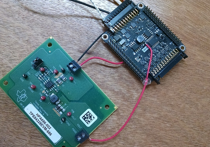
We picked up the eval kit, patched it into a M2-B interface board, as seen here:

and got the following results:

No load on 5V rail: 0.7mA @12V

4.7K Ohm load on 5V rail: (1.0mA @5V) 1.1mA @12V

860K Ohm load on 5V rail: (5.7mA@ 5V) 3.3mA @12V

Note: These numbers do not include the "protection circuitry, which adds about 1mA to 12V current. We’ll look into improving this more.

Outcome: Not bad! We’ll add this change to the list for release M2. We’ll also change the switched rail for CAN transceiver to constant power. This way, we can also wake on CAN activity. The transceiver draws 1mA @ 5V in silent (receive-only) mode.

Awesome! Glad to hear its a simple fix. Interesting that the cause all along was the voltage regulator.

Is the TPS54328 AEC-qualified for automotive use? I didnt see anything in the data sheet mentioning automotive use.

I know it probably doesnt matter “real world” as long as everything is filtered and max voltage is clamped to not allow over 18v to enter the regulator…but its still nice to see that a component is specifically AEC-qualified…

Would it be feasible to incorporate the larger 14-pin version of the TH8056 SWCAN transceiver on the board?

The 14-pin version has the voltage regulator control/enable output…so on GM vehicles with SWCAN, you could have the TH8056 control the regulator directly, which would completely shut down the Macchina for “zero” current draw…and then turn on the voltage regulator when a high-voltage-wakeup signal is received from the SWCAN bus…

Last question…if we were to buy a TPS54328 and (very carefully, with a hot air gun) swap it out on the Macchina board, would it work properly without replacing any other components?

I know it’s a bit late, but I found this an interesting read on Power Saving.
Not the same processor, but might help with some leads, you’re already onto the regulator.
http://gammon.com.au/power
Cheers
W