A word of warning regarding the under the hood M2

Hi, my name is Collin and last night I did something dumb. I blew up my laptop with an M2. I’m 1 day sober for not blowing up hardware.

I’d like to (hopefully) prevent anyone else from doing the same dumb thing. First a little background. The UTH version has a 24 pin connector on one side that handles all of the automotive signal buses (CAN, SWCAN, etc). The other side of the thing has a 26 pin connector with the 12V switched ground outputs, etc. The problem is that they’re basically the same connector just 2 pins different. The 24 pin connector fits very nicely into the 26 pin connector’s socket. One of the little tabs goes right in, it all fits nice and snug and without a very careful look it also looks exactly like it went right into the socket. All of the pins connect perfectly well. The problem here is that the 24 pin connector has a 12V input pin. If you happen to have 12v on that pin and you accidentally put the 24 pin connector into the 26 pin socket you will end up backfeeding 12V into the M2. This is fatal to your M2. Do not do it. You get smoke, you get popping, you get a big sad. But, also, that backfeed will run up your USB cable should you have one installed. This is also fatal to your computer that was attached. This will give you an even bigger sad and you’ll have a frowny face for a long time. Don’t have a frowny face for a long time. Don’t put the wrong plug in the wrong socket.

For all of you with an UTH model, I’d recommend you use a paint marker to mark different colors across the two plugs so that you don’t ever mix them up. Also, be more careful than I was. The automotive connector side is opposite the sdcard slot.

2 Likes

Sorry to hear that Collin, I was worried about the same thing happening to mine when I was looking at it today. I MAY just install the not used one without any wires to insure I don’t do the same thing. Might be a good plan to consider using a different socket for one side so it can’t happen to anyone else.

2 posts were split to a new topic: Under-the-hood Pinout description

Yes, sorry to hear about this Collin. A huge bummer. We’ve been talking about how to fix this for the next revision.

One solution that was mentioned was to use a 16 or 18 pin connector (instead of 24) so it is more obvious which connector goes where. It will still be possible to plug the 16/18 pin connector into the 26 pin connector socket, but visually, the connectors won’t look so similar.

Color coding is another option. Any other ideas out there?

Any way to switch the sex of the connector and make the wire side male and the board side female?

You can normally get connectors that are keyed at the top.Basically a tab, you could get one with 1 tab in the middle for the smaller socket and 2 with each on each side on the other connector.

You see this often with automotive connectors when more than one of the same style connector plugs into a module.

Or common with ribbon cables… Ribbon cable connector might be best solution as it likely would fit into the same holes…

Here is an example of what I mean. This one has a notch in the middle:

https://www.alliedelec.com/images/products/Small/70042782.jpg

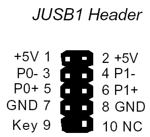
Another method is to use like what a motherboard USB header does and may be much easier to do (Clip a pin and fill in the hole on the socket. MIGHT be able to be ordered special that way). This option could be a retro fit on current setup.

Looking at the schematics there are unused pins on the “Accessory” header and a bunch of grounds on the ODB connector. You could use one or more of those unused pins in the Accessory header and use them to make a Key as well as use one of the ground pins on the ODB side. In the case of the ground, if that line is needed then just connect it on the board to one of the other pins.

Here is an example of the USB header type keying: