
Based on cursory research, I’ve discovered my 2006 Outback uses CANBUS internally (and has a lowspeed + highspeed bus,) but only exposes basic SAE J1850 on the OBD port. I’m trying to figure out where in the dash wiring would be the least risky and invasive place to tap off the CANBUS and +12V accessory power. Has anyone else worked on this era of Subaru who might have any suggestions for where to do this?
Alternatively: Would using SAE J1850 be low-latency enough to be useful for pulling the manifold pressure for the boost gauge? It’s unclear whether or not it’ll have similar problems to ELM327 clones wrt latency and polling rate.
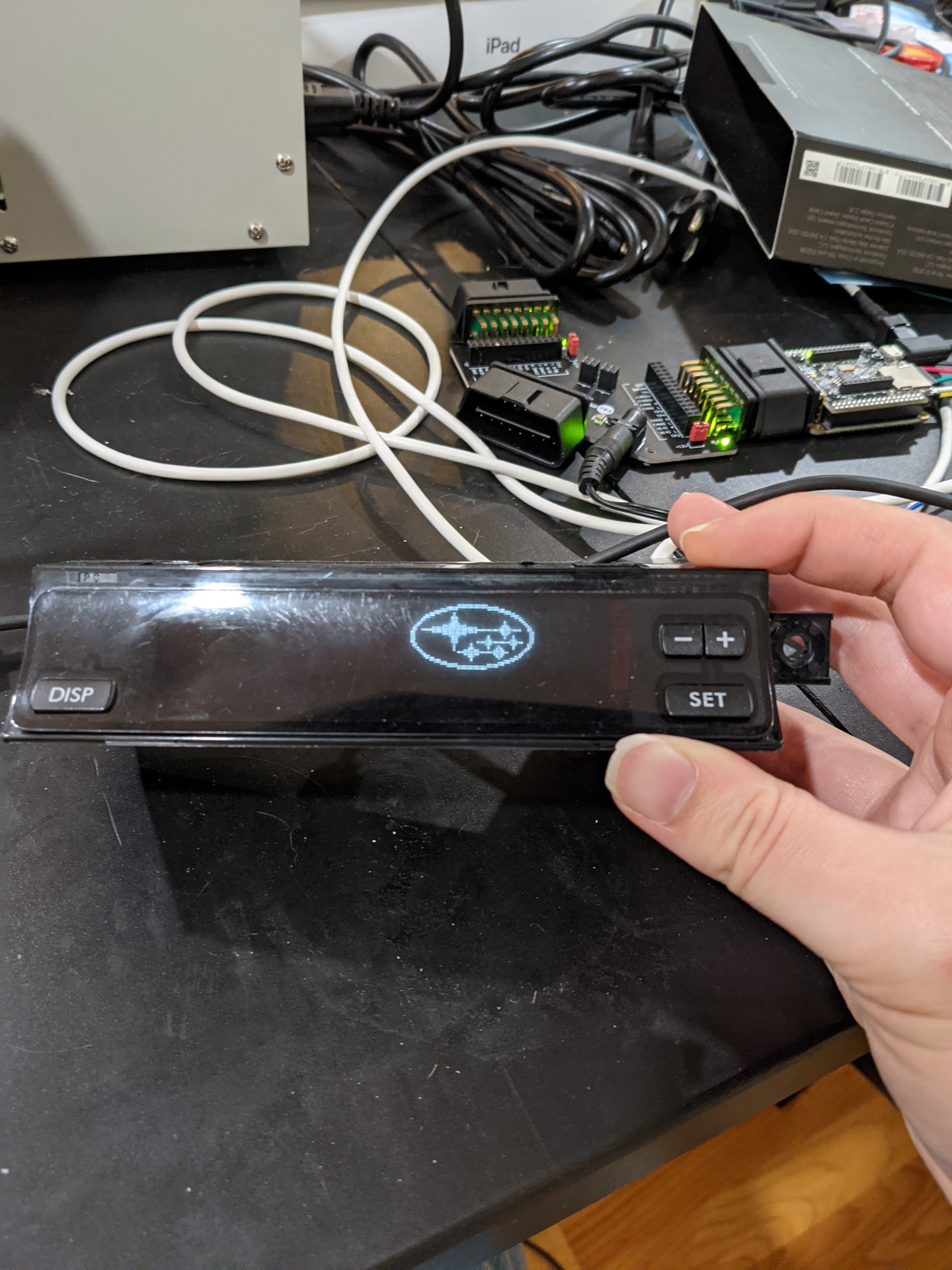
Here’s a preview of where I’m going with this; it’s a Noritake GU128X32D-D903S VFD on a custom board behind the smoked plastic where the stock VFD clock and trip meter were. Fully graphics capable, daylight readable, plan on adding more functions (like displaying the knock sensor count) in addition to the original goal of having a boost gauge.
(Board design credit to https://twitter.com/cpan_pevans)
I would say you need to do a little more research. CANBUS was not mandated to be used by all until I believe 2008 so it was not uncommon to find some vehicles that had both just prior to. One vehicle I am familiar with this is the GM Full sized truck. In the 2003-2005 trucks they had the J1850 VPW bus for all features. In 2006 they added CANBUS for the engine related controls but the J1850 remained for all of the less necessary features thus allowing reuse of the older modules etc until the complete new models in 2007 which were full canbus.
So in short the 2003-2005 had J1850 VPW for all functions.
2006 had J1850 for convenience and support functions such as lighting with CANBUS for engine related controls.
2007 had CANBUS for engine related controls and things that need rapid response. They used SWCAN which is a slow speed, single wire version of CANBUS for convenience and support functions.
The common thread between all of these was the BCM was the bridge between these features and brought all of these to the OBD port. I suspect that you will find that any CANBUS ports are brought out to your OBD port. In later model years the BCM does some security to attempt to prevent unauthorized access to the databus but not likely they did in 2006. You will likely find the Databus is available on your OBD port. I would also suggest that if it does indeed have J1850 that the low speed bus you are seeing is J1850 and not Canbus. You will likely want the Canbus, or highspeed bus.
The M2 can handle 2 1,000k baud connections without dropping any packets as it is significantly faster than any ELM327 modules. So it is more than fast enough for your project.
The first step is to pull your OBD connector and check it for how many wires it has connected to it. Then look at what wires go to what ports. Manufacturers are not in the practice of fully populating ports without a reason for them. The pins they are connected to will tell you what buses your vehicle supports. The BCM for your car should pretty much just be a passthrough. The Diagnostic tools generally talk to the modules directly to allow them to do updates and check functions.
Please note that this information is based on what I understand about GM vehicles prior to 2010 and could be different from your vehicle. You also need to find out what variation of J1850 your car supports. VPW or PWM. The libraries have VPW code but as far as I know, no one has gotten the PWM working.