Support for j1850 VPW/PWM?

How does the Macchina/Due handle “pulseIn” compared to the Uno?

Is the Macchina/Due serial USB slower than the regular old FTDI chip on the Arduino Uno? Could that be messing things up?

In any event, the Macchina isnt even reading the J1850 pulse times correctly…so even at a very basic level, something is broken…whether its the code, or the Macchina’s interface circuit.

This same code works fine on an Arduino Uno and “proper” J1850 transceiver chip.

Can you try storing an array of values big enough to store a whole frame and just display those when the frame is done so you can see what the timings are? That would tell if the serial port is the issue.

I have a hunch it has nothing to do with the Arduino and is just the interface board.

Could always try connecting an Uno to the M2 if you have one of the M2 processor prototype boards that came with the dev kit and try doing it that way? Connect your own pins to the ones on the system. That would tell if it was the Due or the Uno but I am suspecting the edge detection is too tight and needs to be loosened up. While I am not a hardware guy, I would hope that adjusting the resistors may allow adjusting the edge detection to allow a wider range. Just shooting in the dark of course.

OK…well this isnt good.

I have a Due prototype board here…so I hooked up the MCZ33990 chip to the Due prototype board, and uploaded the same sketch.

It reads/measures the pulses CORRECTLY… 64/128uS.

I cant think of any explanation other than theres something seriously wrong with the Macchina’s J1850 VPW circuit/design???

Let’s step back a minute. We took a M2, connected to a emulator and probed the circuit.

Top waveform is Pin 2 of the OBD2 connector. Bottom waveform is “J1850_VPW_RX” signal that goes directly into the processor.

Looks pretty close to me, but we’ll keep investigating.

Any chance you can take a screen grab of a similar setup using the transceiver chip?

My scope (Rigol DS1052) is broken currently…the rotary encoders for the adjustment knobs are all messed up, so its useless.

I think the Due’s serial.print is slow, or messes up/blocks the operation of the processor.

When switching between monitoring the pulses with native USB and programming USB…the readings are different.

Neither readings match the “correct” stuff from the Arduino Uno (direct serial via FTDI/CH340)…but they are different.

So I guess I need to get it to read all the pulses to a cache, then dump the cache to the serial.print window…just to make sure the USB/serial isnt slowing things down.

The real trick is to just get that original sketch working, the one that actually successfully logs J1850 bus traffic on the Uno.

The timer (TIMSK1) stuff is very different on the AVR and ARM processors…so we need to “transpose” that sketch that works on my Arduino Uno into something that’ll work on the Due/Macchina.

I will do what I can to update the program to work with the Due. I will also order some of the chips you are using and hook them up in the next week or so to start working on the driver. If I write a driver for that chip in a Due then the only things that are different are the power on and selector for the M2. When we can resolve what the issue is then it SHOULD work.

This way I can make it so it can work with more than one channel if I so desire so while it will work with M2 if someone wanted to grab a couple and throw them on a Due to do MIM research they can easily.

Rodney

Stupid question/thought…

If I disconnect the processor board of the Macchina, and attach the breakout board…and then tie the “VPW Rx” pin of my Arduino Uno setup to the “VPW Rx” on the Macchina breakout board…shouldnt that theoretically work? To test the VPW circuit of the Macchina.

That would work but first you should fix your sketch… You removed some lines that will bonk the sketch and not make it work.

I suspect you put those lines back in and you may have a different result…

pinMode(PS_J1850_9141, OUTPUT);
pinMode(PWM_nVPW, OUTPUT);
//Turns on power supply to J1850 circuit.
digitalWrite(PS_J1850_9141,LOW);
//Turns on VPW
digitalWrite(PWM_nVPW, LOW);

Those are REQUIRED… Note I think the ,LOW on the last one is missing on my code for some reason…
But try that… Might be the issue all along. Not sure why you commented those lines out.

If I can get a copy of the exact sketch you used and the commands you used from the ELM device I will see if I can duplicate it. I have both a UTH and a UTD M2 and can try it with both.

I have an STN based USB cable which will be slightly different but should act the same.

Rodney

I believe you’ll want to bring PS_J1850_9141 HIGH to bring power to the circuits.

http://docs.macchina.cc/m2/technical-references/pin-mapping.html#power-supplies

Yes you are correct. I changed it on my Github. Again I will try testing this weekend to verify if there is an issue.

I already tried correcting that issue, still doesnt seem to work.

I think we might have to use the “DueTimer” library…?

I think this is the equivalent way to measure pulses/interrupts with high accuracy on the Due.

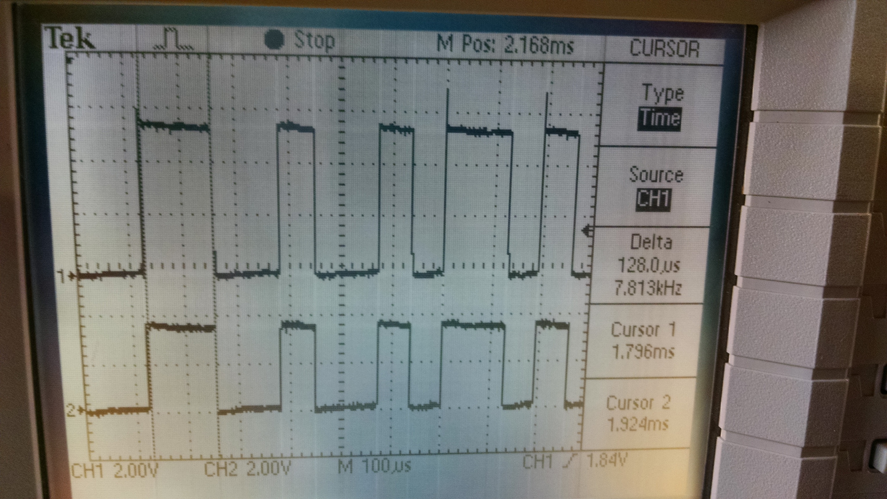
This at least does something with the Due…

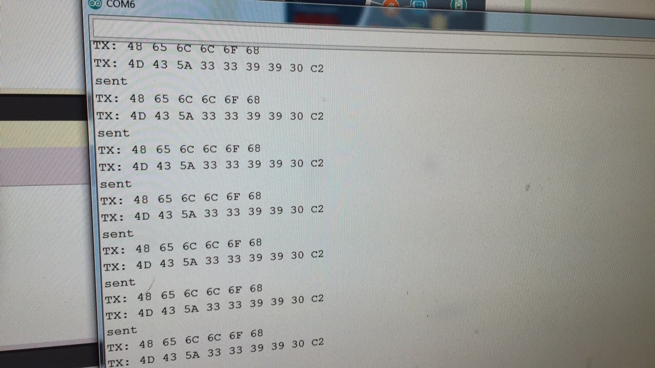
it does detect the start of frame properly, so its a start.

I dont know why it seems to stop working after its detected the SOF though.

//
// J1850 decoder, v1.5
// Mats Ekberg (c) 2013
// 
// This software decodes the binary data stream from a J1850 compliant 
// OBD2 device. Using just one digital input for the data stream and
// transmitting the decoded data on the UART.
//
// http://www.systemconnection.com/downloads/PDFs/OBD-IIJ1850Whitepaper.pdf
//
// Chip:  Arduino Mini Pro w ATmega168 at 16MHz
//
#include <DueTimer.h>

// I/O and interrupts. Pin/Int
// UNO:   2/0, 3/1. 
// Mega:  2/0, 3/1, 21/2, 20/3, 19/4, 18/5
#define J1850_PIN  15
#define J1850_INT  15

unsigned long tstamp2;
unsigned long delta2;
unsigned long longbit2;
unsigned long shortbit2;
unsigned long abyte2;


// Timing for start of frame
#define SOF_TIME      200
#define SOF_DEV        18

// Timing for end of frame
#define EOF_TIME      200
#define EOF_DEV        18

// Timing for a long bit pulse
#define LONGBIT_TIME   128
#define LONGBIT_DEV     16

// Timing for short bit pulse
#define SHORTBIT_TIME   64
#define SHORTBIT_DEV    15

// timeout after 250 microsec
#define  TMR_PRELOAD (65536 - (EOF_TIME*16))

#define TMROVF_INT_OFF   Timer1.stop(); 
#define TMROVF_INT_ON    Timer1.start(); 
#define TMROVF_INT_CLR   Timer1.setPeriod(0);


// forward decl
void j1850_interrupt(void);

volatile boolean idle = true;
// Storage, max 11 data bytes + CRC
#define BUFSIZE 13
volatile uint8_t msgbuf[BUFSIZE];
volatile uint8_t msgLen;


//
// Initialization
//
void setup(void) 
{  
  pinMode(J1850_PIN, INPUT);
  Serial.begin(115200);
  delay(2000);
  Serial.println(F("DUE_j1850decoder/v1.5"));

  TMROVF_INT_OFF;
//  TCCR1A = 0;
  Timer1.setPeriod(TMR_PRELOAD);  // preload timer 65536-16MHz/256/2Hz
//  TCCR1B = _BV(CS10);  // no prescaler, start timer 

  idle = true;
  msgLen = 0;
  attachInterrupt(J1850_INT, j1850_interrupt, CHANGE);
  interrupts();
}


//
// Background loop - print message when available
//
void loop(void)
{
  if (msgLen > 0) {
    Serial.print(F("> "));
    for (int i = 0; i < msgLen; i++) {
          if ((i == 3) || (i == msgLen -1)){
        Serial.print("   ");
      }
      if (msgbuf[i] < 16) Serial.print("0");
      Serial.print(msgbuf[i], HEX);
    }
    Serial.println();
    msgLen = 0;
  }
}

//
// Interrupt routine for changes on j1850 data pin
//

volatile unsigned long lastInt = 0;
volatile uint8_t bitCnt;
volatile long delta;
volatile unsigned long tstamp;
volatile uint8_t aByte;
volatile uint8_t buf[BUFSIZE];
volatile uint8_t bufIdx;


void j1850_interrupt(void)
{

  tstamp = micros();

  uint8_t pin = digitalRead(J1850_PIN);

  // reload the overflow timer with EOF timeout
  Timer1.setPeriod(TMR_PRELOAD);         
  delta = tstamp - lastInt;
  long longbit, shortbit;

  if (idle)
  {
    if (pin == 0) 
    {
      longbit = delta - SOF_TIME;
      if (abs(longbit) < SOF_DEV)
      {
        Serial.println("SOF");
        // found SOF, start header/data sampling
        idle = false;
        bitCnt = 0;
        bufIdx = 0;
        aByte = 0;
      }
    }
  } 
  else
  {
    shortbit = delta - SHORTBIT_TIME;
    longbit = delta - LONGBIT_TIME;
    if (abs(shortbit) < SHORTBIT_DEV) {
      // short pulse
      if (pin == 0)
        // short pulse & pulse was high => active "1"
        aByte = (aByte << 1) | 0x01;
      else
        // short pulse & pulse was low => passive "0"
        aByte = (aByte << 1) & 0xFE;
      bitCnt++;
    } 
    else if (abs(longbit) < LONGBIT_DEV) {
      // long pulse
      if (pin == 0)
        // long pulse & pulse was high => active "0"
        aByte = (aByte << 1) & 0xFE;

      else
        // long pulse & pulse was low => passive "1"
        aByte = (aByte << 1) | 0x01;
      bitCnt++;

    } 
    else {
      // unknown bit, reset
      TMROVF_INT_OFF; 
      idle = true;
      lastInt = tstamp;
      return;
    }

    if (bitCnt >= 8) {

      buf[bufIdx++] = aByte;
      bitCnt = 0;
      if (bufIdx >= sizeof(buf)) {
        // too many data bytes, error
        TMROVF_INT_OFF; 
        idle = true;
      } 
      else {
        // if all is ok, start the EOF timeout
        TMROVF_INT_CLR; 
        TMROVF_INT_ON; 
      }
//              abyte2 = aByte;
    }
  }
  lastInt = tstamp;
}

// Timer overlflow interrupt
// Occurs when the EOF pulse times out the timer
//
ISR(TIMER1_OVF_vect)  
{

  Timer1.setPeriod(TMR_PRELOAD);  
  TMROVF_INT_OFF; 

  // copy the data so that we can start to fill the buffer again
  // but only if the buffer has been consumed in the background
  if (bufIdx > 0 && msgLen == 0)
  {
    memcpy((void*)msgbuf, (const void*)buf, bufIdx);
    msgLen = bufIdx;
  }
  idle = true;
}

Good practice
Should you not test the incrementing of the buffer pointer “bufIdx++” will not exceed the bounds of the buffer before writing to the buffer otherwise you could start writing to random areas of memory & then all hell would break out
’’'
if (bitCnt >= 8) {

  buf[bufIdx++] = aByte;
  bitCnt = 0;
  if (bufIdx >= sizeof(buf)) {
    // too many data bytes, error
    TMROVF_INT_OFF; 
    idle = true;
  } 
  else {
    // if all is ok, start the EOF timeout
    TMROVF_INT_CLR; 
    TMROVF_INT_ON; 
  }

// abyte2 = aByte;
}

‘’’

Now that I have my setup so I can actually start working on it will see how this goes…

To tired to do anything tonight but going to try to get this going tomorrow. I now have my UTH module wired to my simulator. Just have to add power to it and test it out. Assuming this works I should be able to start testing myself shortly.

Rodney

Ahh shoulda left that out.

The abyte2, delta2, longbit2, etc

was purely just for debug purposes, I wanted to see where the sketch was going in real life, and what the Macchina was actually reading/seeing.

Ignore them…

Here is another library I found…

1 Like

Ok…now have complete success with my Uno and MCZ33990!!!

I can now send and receive messages on J1850-VPW.

I found this library, but I had to modify it and invert some things before it would work with the MCZ33990…but it works now as you can see in the pics.

Im gonna try it on the Macchina now that I know it 100% works for receiving AND sending using a “proper” J1850 transceiver chip…now to see if it works the same with the Macchina’s “DIY” transceiver setup. :grin:

1 Like

Cool, which library was that?

Since you have a working library I will wait to see what you find out with the M2.