Support for j1850 VPW/PWM?

Is anybody working on documenting the GM Commands?

I own a 2002 Chevy Trailblaizer LT and a 2003 Chevy Trailblazer LS

The LT has keyfob and a bunch of exta options, the LS does not…

one thing i want to do is learn the Door Lock/unlock command and build a keyfob… ( Or figure out how to enable it in the BCM ) … the LGM accepts a programmed keyfob on my 2002, but the 2003 just “iqnores” the program command, and if i program a keyfob to the LGM the BCM iqnores the unlock command from it… However, a aftermarket Directed Electronics 457G sends the unlock command without issue… I wonder what the difference is between the LGM and the Directed Device. and why the BCM accepts the 457G commands and not the LGM…

I can’t wait for my Macchina…

Look at the source and destination of the commands. I would suspect they are different in each case. Not sure when the Trailblazers would have gotten updated but the full sized trucks had a significant portion of the truck rewired from 2002-2003. In my 2003 avalanche the passenger door module included the receivers for both TPMS and keyless entry. If these options are turned off in the door module they won’t work. However the door modules themselves talk to one another and will still send and receive the lock/unlock commands. Based on the actions of my Compustar alarm system and its connected drone module I believe one unlock command will unlock just the drivers door and if followed within a specific with another unlock command will unlock all 4 doors. I believe the lock command is only given once to lock all 4.

Since GM tends to reuse commands I would suspect the same command will work across models. Only way to know for sure is to try for yourself.

I will be doing some stuff to document as much of my truck as possible and will be looking at providing a location online to access that information. If you look there is a posting on this forum that mentioned the GMLAN BIBLE. This MAY contain the proper commands to do the lock/unlock functions for your vehicle.

Rodney

The 2002 trailblazer has the same electrical architecture as the 2003-2007 GMT-800.

So all of the messages and modules will be the same.

Hey I haven’t had time to jump on this as I would have hoped. Been tied up with some unexpected mechanical issues with one of my vehicles. I have been trying to read the due_can driver and the m2ret stuff any free time that I have had but been very limited so far this summer. I have downloaded all the information here for building the j1850 reader and will start trying to make a reader JUST for the j1850.

My current plan of action is to start with the code bases you guys posted and working off the first one, since arduino based, and see how far I can get with it. I expect to at least look through the second one to see how well I can integrate any additional stuff. Since that has both j1850 protocols we will see if I can get both working.

Ok so I have found some other projects out there doing J1850 vpw. One was a very simple scan utility. Got a lot going on this weekend but will try to get a test lab setup using this Chinese ODBII simulator, a y cable and an STN adapter. My intent will be to get the Simulator and STN adapter talking then try to look at it from the M2. If the code I have works it is only a few lines of code. Will tinker with it and see what I can get out of it. The communications between the STN adapter and the Chinese simulator are simple and I have already done that so hopefully I will have some sign of life for the VPW soon. Realistically the projects I have seen so far, and I have tracked down about 6 different projects, are all similar and none seemed to be completely finished. So we shall see how this goes. My intent will be to eventually get it to mesh with the M2RET driver but for now I will be trying to get it to work on its own, solidify it, then move to the M2RET project.

Rodney

1 Like

Rodney-

Just wondering if you’ve had a chance to mess around with J1850 VPW anymore?

All of the J1850VPW arduino stuff Ive found so far (very limited, as J1850 VPW was mostly only used by GM and Chrysler) is basically just devoted to acting as a scan tool to read some simple SAE PID’s.

What Im really looking for/would like to do is create something that works just like the typical/common MCP2515/CAN bus libraries, except for J1850VPW.

Ie, where you can directly specify actual 8-byte messages and send them out on demand, listen for/read all messages with XX YY ZZ header, etc…

As you know, GM was pretty unique/ground-breaking/ahead of the times in the late-90’s/early 2000’s in that they used J1850 VPW all over the vehicles with dozens of interior/chassis modules all on one common J1850 bus before they rolled out CAN.

All other manufactures “pre-CAN” had things wired discretely, and used J1850/ISO/etc ONLY for OBD compliance between scan tools and the engine control modules. GM fully used J1850VPW just like all modern vehicles use CAN today.

I think the basics are there in some of the existing limited “J1850 VPW scan tool” Arduino libraries…they just have to be expanded and overhauled to allow easier use, and also ensure that they arent “blocking” to the rest of the main M2RET/Due program.

Also, even commercial J1850 VPW bus analysis software is hard to come by.

Even the industry standard Vehicle Spy dropped support for it because Phillips stopped making the AU5780 J1850 VPW transceiver chips, and apparently Intrepid Control Systems didnt want to redesign their interfaces to use a “nuts and bolts” makeshift J1850 transceiver using transistors and diodes. Kind of ridiculous given the price you pay for it, but oh well.

Besides the average ELM327-based devices and using a clunky serial terminal, there is still one inexpensive option ive found that works very well and is super easy to use: http://www.dashlogic.com/passthruscope is the software.

It works beautifully with the GM MDI, which you can find chinese clones of on Aliexpress for $150.

So for $150, plus the cost of a Passthroughscope subscription, you can have a nice “SavvyCAN-esque” setup for working on J1850VPW. The software also supports J1850PWM, ISO, SWCAN, and dual-wire CAN.

Its useful in that you can log multiple busses simultaneously too…the ability to actually log and analyze J1850VPW and CAN simultaneously is pretty cool…between 2007 and 2013, GM had some vehicles with J1850 for all body/interior comms, and CAN for engine/trans/chassis comms (using either the BCM or ECM has the CAN <–> J1850 gateway/translator). The C6 Corvette, 2007+ trailblazer, 2007+ Colorado, 2004-2006 Equinox are some examples that mixed CAN and J1850.

Passthroughscope is literally the only option available right now that can log both simultaneously, and I think would be helpful in developing/testing J1850VPW support for the Macchina.

Ben

I have been limited in my time currently due to unexpected vehicle repairs and working on average 60 hours a week. Hopefully the vehicle repairs are done for now (keeping fingers crossed) and work has hired a couple new people but we have some “hot” projects and I have been picking up on the mechanical repairs quickly. So I have been tasked with doing repairs on stuff normally saved for the mechanics with 10+ years of experience. I was promoted to a joint operational/mechanical position less than a year ago and finding time this summer to do projects have been far more limited than I expected.

Currently reworking my workbench to make it more efficient but hopefully I will be able to get a scanner up and running shortly with M2. I will try to get it up and running on its own using one of the libraries I have found and go from there. My expected method of attack is to convert one of the current libraries to work with M2, build it up so it will run with the current software. It will be compatible with the ELM driver and the SocketCan V2 protocol. It wouldn’t be too difficult to get working with the MDI protocol if there is documentation out there to do so.

Once I have it up and running as a scanner the writing to the port shouldn’t take much more. I have drivers that also do that but the one very simple scan only driver I found is for older Arduino. I should be able to get it to work but should be able to update it to the DUE interface once up and running.

I HOPE to modify SavvyCAN to read from the M2 from any device supported so it can be used for CAN, j1850, Lin etc…

Tim at GRIMM did tell me that he is interested in working with me on some of the hardware aspects since GRIMM has all of the things I want to do on their todo list. But that won’t happen until after DEFCON.

Rodney

I should also point out that a couple of the libraries I have also have a library of PID type definitions too so I will likely modify that library to work with whatever I have going and offer it as an add on for running it stand alone.

My original plan was to spend at least one full day a week on this but haven’t been able to spend more than a couple hours a week on this unfortunately.

Rodney

Found a couple things…but havent had a chance to really look at them in depth or try them out.

This one is more extensive, but unfortunately its for J1850-PWM, not J1850-VPW. :confused:

The trick would be to make the library/code so its “non-blocking” and can work in the background without tying up the whole program…especially if you’re working with CAN and J1850VPW simultaneously, since CAN is wayyy faster and more rapid fire than J1850…you dont want the entire program stalled (and potentially missing CAN messages) while its busy sending/receiving J1850 messages.

Ben

2 Likes

Will make note of that library once the VPW one is done. I hopefully will have time to work on it this week.

I plan to get something up and running which will likely be blocking at first. I plan to use the idea of the mailboxes with the due_can drivers and extend that once it is working. I will try to make it not depend on the due_can library but live with it if it is there.

Since there really isn’t a library designed for the Due it is working from scratch. Using the interrupts and mailbox type of buffering system it will be non-blocking but initially I just want to get it communicating. But hopefully build from there. I just have to have time to work on this which has been hard to come by.

The guy I hope to pick his brain is still in Las Vegas so will be another week or so before I can pick his brain about how this stuff works too. Looks like my classes for the fall should be easy so I will likely actually have more time to work on this and other M2 related projects.

Just tried testing my lab. Had to move it to another computer and the power supply I was using was wrong voltage. Ordered a new one and should hopefully be back up in a couple days for testing… Running the ODBII dongle and simulator on same computer then running my M2 from my development computer.

Just wondering if Rod or anyone else has made any additional J1850 VPW progress?

Due to the specific timing of receiving the messages…im not sure it would be possible to make this code non-blocking?

Maybe could use “micros”…when it receives a pulse on the J1850 VPW Rx, it takes a snapshot of the current microseconds of runtime?

But still then you’d be fighting any other loops or processes, such as sending CAN messages, etc. You’re literally bit-banging it from scratch. Maybe im underestimating the power and speed of the Cortex-M3 in comparison to the speed of 10.4k VPW though??

What I wouldnt give for a simple J1850 VPW library thats as easy to use/well implemented as all the dozen+ CAN libraries there are out there!! :grin:

Found this good article…

so it looks like the LONGEST possible J1850VPW message, from start of frame, 3 byte header, 8-byte message, CRC, to end of frame, is about 13 milliseconds.

Due to timing, and the passive/active states of the bus, it could be much shorter. But 13mS is the absolute longest the Macchina would be tied up for if we did NOT make fancy non-blocking code.

Considering CAN is much faster, would this pose any problems? I know both the CortexM3’s internal CAN controller and the MCP2515 for SWCAN have buffers…but still 13mS seems like a long time for a program to be stalled.

But I guess we have to start somewhere…

http://www.cnblogs.com/shangdawei/p/4769620.html

(note, in the article, the guy mixes up milliseconds and microseconds…J1850 VPW timing deals in microseconds of course)

Sorry, I have been busy. Won’t bother you with the issues I have been having. Hopefully sorted out and will slowly be able to get back to this.

Assuming I have my Lab working again this weekend I will try to get something reading the data in the next couple weeks.

As to the Blocking issues… Don’t believe it will be an issue. Will have to see how it works out. The Interrupts can be triggered on a hi, low or change in signal. Worst case may have to work the interrupts at a bit level and go from there. If I am not mistaken the pins that the M2 is hooked to on the Due also have some things that can help such as a frequency counter and such designed to read these things.

Basically we have to roll what the CANBUS transceiver and controller do into code that will handle the J1850 VPW protocols. Shouldn’t be THAT difficult due to the slower speeds but we will see.

I apologize, I haven’t had the time available this summer I had assumed when I picked up this project. Hopefully I can do something productive with this soon. I also want to do some other stuff with the hardware but really have to get this tied down and working before I can do much else with it.

Stumbled upon this library that might be useful for this project - should make reading and writing PWM signals easier.

2 Likes

Will look into it… I have been real busy with school. Next two weeks are hectic but got some more parts in to make some changes to my lab and hopefully will have that back up and running this weekend so I can actually do something.

Im revisiting J1850-VPW…

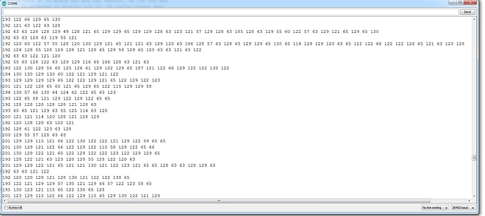
Just starting some very basic initial tests, made a simple sketch to measure the pulse widths each time a message is received from the J1850-VPW bus.

You can see the intitial ~200uS pulse that indicates the beginning of the message, etc.

And then the actual pulse widths of the message bits themselves.

Gotta start somewhere…

Ben

@dmaxben
So what are you using for this sketch? M2? MCZ3390?

I am not 100% sure what I am seeing.

I would guess your showing bits and the timing would be related to the actual bits being seen? But is curious because of the format. I would have expected a more square output.

This is literally just an Arduino Uno hooked up to the MCZ33990.

What you are seeing is simply the length of each “high” pulse that is being detected on the J1850 bus.

Not sure what you mean “a more square output”

You need to read the J1850 hardware layer spec and then that picture I posted will make more sense.

~200uS “high” pulse signifies the start of a message…

A ~128uS “high” pulse OR a ~64uS “low” pulse denotes a “0” bit

A ~64uS “high” pulse OR a ~128uS “low” pulse denotes a “1” bit

The transition flip-flops depending on what the last bit sent was…ie if it wants to send the bits 0,0,1,0,1,1…

it does:

200uS high start of message…bus is high now, so the next bit has to be low regardless of whether its a 1 or 0

64uS low pulse for “0” (because the bus was previously high)
128uS high pulse for “0” (because the bus was previously low)
128uS low pulse for "1"
128uS high pulse for "0"
128uS low pulse for "1"
64uS high pulse for “1”

Make sense?

1 Like