Support for j1850 VPW/PWM?

I should also point out that a couple of the libraries I have also have a library of PID type definitions too so I will likely modify that library to work with whatever I have going and offer it as an add on for running it stand alone.

My original plan was to spend at least one full day a week on this but haven’t been able to spend more than a couple hours a week on this unfortunately.

Rodney

Found a couple things…but havent had a chance to really look at them in depth or try them out.

This one is more extensive, but unfortunately its for J1850-PWM, not J1850-VPW. :confused:

The trick would be to make the library/code so its “non-blocking” and can work in the background without tying up the whole program…especially if you’re working with CAN and J1850VPW simultaneously, since CAN is wayyy faster and more rapid fire than J1850…you dont want the entire program stalled (and potentially missing CAN messages) while its busy sending/receiving J1850 messages.

Ben

2 Likes

Will make note of that library once the VPW one is done. I hopefully will have time to work on it this week.

I plan to get something up and running which will likely be blocking at first. I plan to use the idea of the mailboxes with the due_can drivers and extend that once it is working. I will try to make it not depend on the due_can library but live with it if it is there.

Since there really isn’t a library designed for the Due it is working from scratch. Using the interrupts and mailbox type of buffering system it will be non-blocking but initially I just want to get it communicating. But hopefully build from there. I just have to have time to work on this which has been hard to come by.

The guy I hope to pick his brain is still in Las Vegas so will be another week or so before I can pick his brain about how this stuff works too. Looks like my classes for the fall should be easy so I will likely actually have more time to work on this and other M2 related projects.

Just tried testing my lab. Had to move it to another computer and the power supply I was using was wrong voltage. Ordered a new one and should hopefully be back up in a couple days for testing… Running the ODBII dongle and simulator on same computer then running my M2 from my development computer.

Just wondering if Rod or anyone else has made any additional J1850 VPW progress?

Due to the specific timing of receiving the messages…im not sure it would be possible to make this code non-blocking?

Maybe could use “micros”…when it receives a pulse on the J1850 VPW Rx, it takes a snapshot of the current microseconds of runtime?

But still then you’d be fighting any other loops or processes, such as sending CAN messages, etc. You’re literally bit-banging it from scratch. Maybe im underestimating the power and speed of the Cortex-M3 in comparison to the speed of 10.4k VPW though??

What I wouldnt give for a simple J1850 VPW library thats as easy to use/well implemented as all the dozen+ CAN libraries there are out there!! :grin:

Found this good article…

so it looks like the LONGEST possible J1850VPW message, from start of frame, 3 byte header, 8-byte message, CRC, to end of frame, is about 13 milliseconds.

Due to timing, and the passive/active states of the bus, it could be much shorter. But 13mS is the absolute longest the Macchina would be tied up for if we did NOT make fancy non-blocking code.

Considering CAN is much faster, would this pose any problems? I know both the CortexM3’s internal CAN controller and the MCP2515 for SWCAN have buffers…but still 13mS seems like a long time for a program to be stalled.

But I guess we have to start somewhere…

http://www.cnblogs.com/shangdawei/p/4769620.html

(note, in the article, the guy mixes up milliseconds and microseconds…J1850 VPW timing deals in microseconds of course)

Sorry, I have been busy. Won’t bother you with the issues I have been having. Hopefully sorted out and will slowly be able to get back to this.

Assuming I have my Lab working again this weekend I will try to get something reading the data in the next couple weeks.

As to the Blocking issues… Don’t believe it will be an issue. Will have to see how it works out. The Interrupts can be triggered on a hi, low or change in signal. Worst case may have to work the interrupts at a bit level and go from there. If I am not mistaken the pins that the M2 is hooked to on the Due also have some things that can help such as a frequency counter and such designed to read these things.

Basically we have to roll what the CANBUS transceiver and controller do into code that will handle the J1850 VPW protocols. Shouldn’t be THAT difficult due to the slower speeds but we will see.

I apologize, I haven’t had the time available this summer I had assumed when I picked up this project. Hopefully I can do something productive with this soon. I also want to do some other stuff with the hardware but really have to get this tied down and working before I can do much else with it.

Stumbled upon this library that might be useful for this project - should make reading and writing PWM signals easier.

2 Likes

Will look into it… I have been real busy with school. Next two weeks are hectic but got some more parts in to make some changes to my lab and hopefully will have that back up and running this weekend so I can actually do something.

Im revisiting J1850-VPW…

Just starting some very basic initial tests, made a simple sketch to measure the pulse widths each time a message is received from the J1850-VPW bus.

You can see the intitial ~200uS pulse that indicates the beginning of the message, etc.

And then the actual pulse widths of the message bits themselves.

Gotta start somewhere…

Ben

@dmaxben
So what are you using for this sketch? M2? MCZ3390?

I am not 100% sure what I am seeing.

I would guess your showing bits and the timing would be related to the actual bits being seen? But is curious because of the format. I would have expected a more square output.

This is literally just an Arduino Uno hooked up to the MCZ33990.

What you are seeing is simply the length of each “high” pulse that is being detected on the J1850 bus.

Not sure what you mean “a more square output”

You need to read the J1850 hardware layer spec and then that picture I posted will make more sense.

~200uS “high” pulse signifies the start of a message…

A ~128uS “high” pulse OR a ~64uS “low” pulse denotes a “0” bit

A ~64uS “high” pulse OR a ~128uS “low” pulse denotes a “1” bit

The transition flip-flops depending on what the last bit sent was…ie if it wants to send the bits 0,0,1,0,1,1…

it does:

200uS high start of message…bus is high now, so the next bit has to be low regardless of whether its a 1 or 0

64uS low pulse for “0” (because the bus was previously high)
128uS high pulse for “0” (because the bus was previously low)
128uS low pulse for "1"
128uS high pulse for "0"
128uS low pulse for "1"
64uS high pulse for “1”

Make sense?

1 Like

So the longest possible message (byte) in terms of how long it takes to transmit, would be:

“10101010” or $AA.

Because that would require 1024uS to transmit (128uS alternating high/low pulses), not including the start of frame (200uS), or end of frame (200uS)…

Quickest possible message is “01010101” or $55…it would only take 512uS to transmit byte value $55.

1 Like

J1850 message can be up to 12 bytes (3 byte header, 8 byte payload, 1 byte checksum).

So, doing the math, it could take up to ~13000uS all said and done from start of frame to end of frame (if the message was $AA $55 $AA $55, etc

up to a max of 13mS just to transmit one message on J1850 VPW. Obviously real world is much quicker because most messages arent the full 8 bytes etc.

Pretty slow compared to CAN. :slightly_smiling_face:

1 Like

So the code logic needs to go:

wait for a 200uS high pulse.

Once it sees a 200uS high pulse, it knows a message is starting.

As soon as the signal drops back low after that, start a timer.

When the signal goes back up high, look at the timer.

—> if timer reading = 64 uS, you know that first bit was a 0.
—> if timer reading = 128uS, you know that first bit was a 1.

(zero out the timer, start it over)

when the signal goes back down load, look at the timer.

—> if the timer reading = 64uS, you know that second bit was a 1.
—> if the timer reading = 128uS, you know that second bit was a 0.

start timer over, watch for the next high/low transition, etc.

Thats the basics…now who’s good at translating that into Arduino code!

1 Like

This library might make using the SAMX8E built-in timers a little easier.

2 Likes

I found the data sheet online…

Basically these chips give a direct connection to the MCU. In your case the Uno. Looks like you can connect all 4 lines directly to IO lines on the Uno.

The battery in takes +12 volts and needs a diode in series to protect against battery spikes.

The LOAD connection needs a resistor between it and the databus connection of 10.6k. This prevents destruction of the chip in the case of the ground being disconnected.

It also needs a 470picofarad capacitor going to ground off the databus line.

This data can be used with the hardware of the M2 so I am posting this here. It describes in short what we really want to know.

Receiver Protocol
The Class B communication scheme uses a variable pulse
width (VPW) protocol. The microcontroller provides the VPW
decoding function. Once the receiver detects a transition on Rx,
it starts an internal counter. The initial “start of frame” bit is a
logic [1] and lasts 200μs. For subsequent bits, if there is a bus
transition before 96μs, one logic state is inferred. If there is a
bus transition after 96μs, the other logic state is inferred. The
“end of data” bit is a logic [0] and lasts 200μs. If there is no
activity on the bus for 280μs to 320μs following a broadcast
message, multiple unit nodes may arbitrate for control of the
next message. During an arbitration, after the “start of frame”
bit has been transmitted, the secondary node transmitting the
most consecutive logic [0] bits will be granted sole
transmission access to the bus for that message.

Editing this message as I understand better how it is working…

Should be simple to write a library to work with either the chip or the M2.

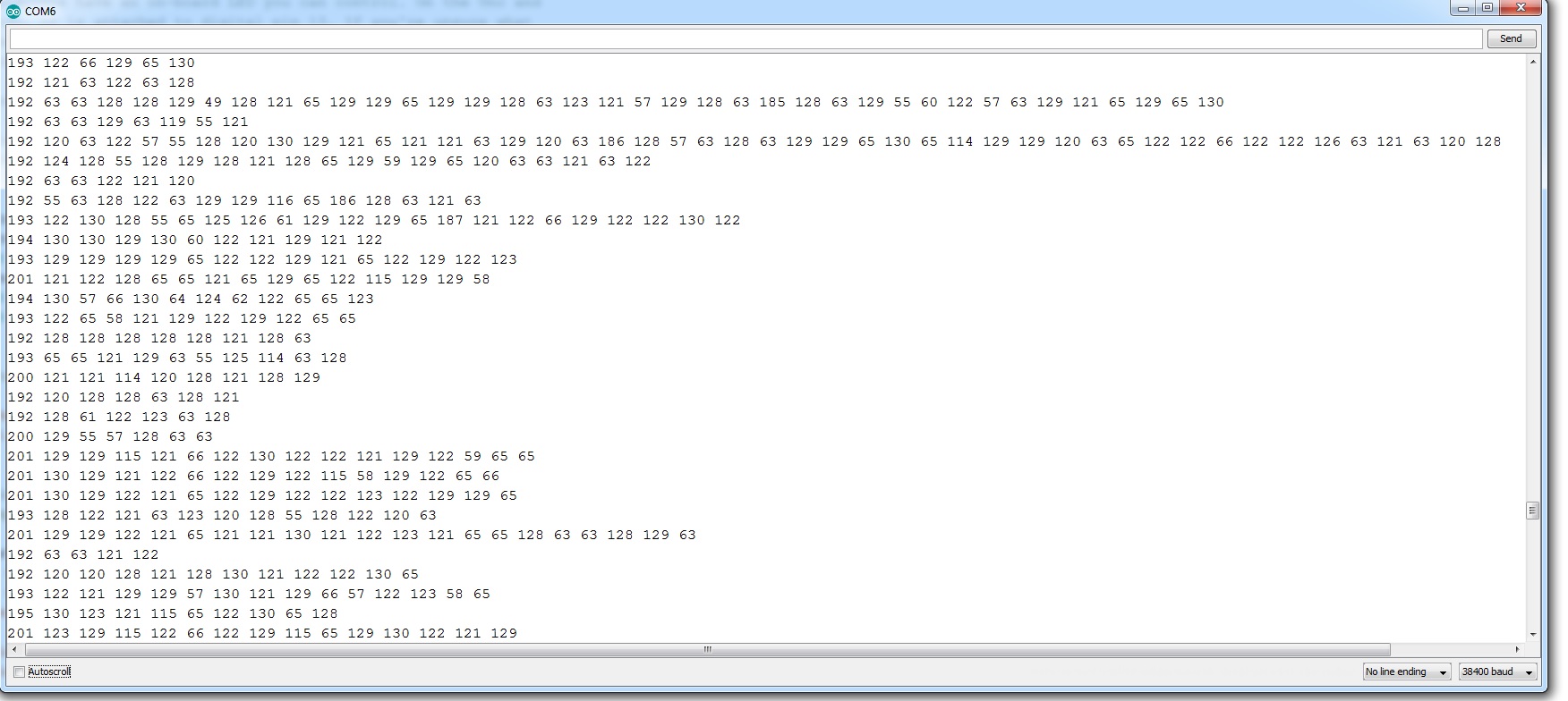
The only difference I see at this stage is that the chip does wave forming for you. Zero trigger is actually anything below 20% of signal. High trigger is anything bigger than 80%. Not sure from the output what the chip actually returns. I am assuming it is returning the microseconds between changes?

So to mimic this the M2 would have to read the signal, start the timer at anything above 80% and stop it at anything below 20%. (This amount allows for differences in the voltages of devices in the bus if I understand properly.)

I am assuming the chip, based on the information given sends out a wave form that is slightly rounded off. Not sure without checking but not sure if the Due will be sending out a square wave or more of a rounded off wave. It appears to be necessary to be curved to pick up the trigger points. When I get my lab working I can probably do some testing to see for sure how it is handled.

So theoretically it should be possible to build a library with only minor changes to the code to support either this chip or the M2.

1 Like

Alllllright alllright alllriiiigghhhtttt… :sunglasses:

it works, for receiving.

I found some existing code online, and after some hacking and modification, it now successfully prints GM J1850-VPW traffic in the serial terminal window.

This is using nothing more than an arduino Uno, an MCZ33990, and a bus load resistor.

3 byte header (space) up to 8 byte payload (space) 1 byte checksum


//==============================================================

#define J1850_PIN  3
#define J1850_INT  1

#define LED_PIN 13


// Timing for start of frame
#define SOF_TIME      200
#define SOF_DEV        18

// Timing for end of frame
#define EOF_TIME      200
#define EOF_DEV        18

// Timing for a long bit pulse
#define LONGBIT_TIME   128
#define LONGBIT_DEV     16

// Timing for short bit pulse
#define SHORTBIT_TIME   64
#define SHORTBIT_DEV    15

// timeout after 250 microsec
#define  TMR_PRELOAD (65536 - (EOF_TIME*16))

#define TMROVF_INT_OFF   TIMSK1 &= (~_BV(TOIE1)) 
#define TMROVF_INT_ON    TIMSK1 |= _BV(TOIE1) 
#define TMROVF_INT_CLR   TIFR1 &= _BV(TOV1)


// forward decl
void j1850_interrupt(void);

volatile boolean idle = true;
// Storage, max 11 data bytes + CRC
#define BUFSIZE 13
volatile uint8_t msgbuf[BUFSIZE];
volatile uint8_t msgLen;


//
// Initialization
//
void setup(void) 
{  
  pinMode(J1850_PIN, INPUT);

  pinMode(LED_PIN, OUTPUT);
  digitalWrite(LED_PIN, HIGH);

  Serial.begin(115200);
  delay(2000);
  digitalWrite(LED_PIN, LOW);
  delay(1000);
  Serial.println(F("j1850decoder/v1.5"));

  TMROVF_INT_OFF;
  TCCR1A = 0;
  TCNT1 = TMR_PRELOAD;  // preload timer 65536-16MHz/256/2Hz
  TCCR1B = _BV(CS10);  // no prescaler, start timer 

  idle = true;
  msgLen = 0;
  attachInterrupt(J1850_INT, j1850_interrupt, CHANGE);
  interrupts();
}


//
// Background loop - print message when available
//
void loop(void)
{
  if (msgLen > 0) {
    Serial.print(F("> "));
    for (int i = 0; i < msgLen; i++) {
          if ((i == 3) || (i == msgLen -1)){
        Serial.print("   ");
      }
      if (msgbuf[i] < 16) Serial.print("0");
      Serial.print(msgbuf[i], HEX);
    }
    Serial.println();
    msgLen = 0;
  }
}

//
// Interrupt routine for changes on j1850 data pin
//

volatile unsigned long lastInt = 0;
volatile uint8_t bitCnt;
volatile long delta;
volatile unsigned long tstamp;
volatile uint8_t aByte;
volatile uint8_t buf[BUFSIZE];
volatile uint8_t bufIdx;


void j1850_interrupt(void)
{
  tstamp = micros();

  uint8_t pin = digitalRead(J1850_PIN);

  // reload the overflow timer with EOF timeout
  TCNT1 = TMR_PRELOAD;           

  delta = tstamp - lastInt;
  long longbit, shortbit;

  if (idle)
  {
    if (pin == 0) 
    {
      longbit = delta - SOF_TIME;
      if (abs(longbit) < SOF_DEV)
      {
        // found SOF, start header/data sampling
        idle = false;
        bitCnt = 0;
        bufIdx = 0;
        aByte = 0;
//        digitalWrite(LED_PIN, LOW);
      }
    }
  } 
  else
  {
    shortbit = delta - SHORTBIT_TIME;
    longbit = delta - LONGBIT_TIME;

    if (abs(shortbit) < SHORTBIT_DEV) {
      // short pulse
      if (pin == 0)
        // short pulse & pulse was high => active "1"
        aByte = (aByte << 1) | 0x01;
      else
        // short pulse & pulse was low => passive "0"
        aByte = (aByte << 1) & 0xFE;
      bitCnt++;

    } 
    else if (abs(longbit) < LONGBIT_DEV) {
      // long pulse
      if (pin == 0)
        // long pulse & pulse was high => active "0"
        aByte = (aByte << 1) & 0xFE;
      else
        // long pulse & pulse was low => passive "1"
        aByte = (aByte << 1) | 0x01;
      bitCnt++;

    } 
    else {
      // unknown bit, reset
      TMROVF_INT_OFF; 
      idle = true;
      lastInt = tstamp;
      return;
    }

    if (bitCnt >= 8) {

      buf[bufIdx++] = aByte;
      bitCnt = 0;
      if (bufIdx >= sizeof(buf)) {
        // too many data bytes, error
        TMROVF_INT_OFF; 
        idle = true;
      } 
      else {
        // if all is ok, start the EOF timeout
        TMROVF_INT_CLR; 
        TMROVF_INT_ON; 
      }
    }
  }
  lastInt = tstamp;
}

// Timer overlflow interrupt
// Occurs when the EOF pulse times out the timer
//
ISR(TIMER1_OVF_vect)  
{
  TCNT1 = TMR_PRELOAD;  
  TMROVF_INT_OFF; 
//  digitalWrite(LED_PIN, HIGH);

  // copy the data so that we can start to fill the buffer again
  // but only if the buffer has been consumed in the background
  if (bufIdx > 0 && msgLen == 0)
  {
    memcpy((void*)msgbuf, (const void*)buf, bufIdx);
    msgLen = bufIdx;
  }
  idle = true;
}

1 Like

I dont know why the code formatting got messed up.

Im not sure if this forum interface supports a insert function to make things easier to read?

The reading part looks to be easy… Writing is going to be interesting because you have to do the arbitration.