Macchina M2 on Raspberry Pi

I’m working on a project that requires CAN to be interfaceable with Python. I would like to use the Macchina M2 to collect ambient CAN data from vehicles. The preexisting code for my project is written in Python, so I would like to avoid using an entirely new language to begin working.

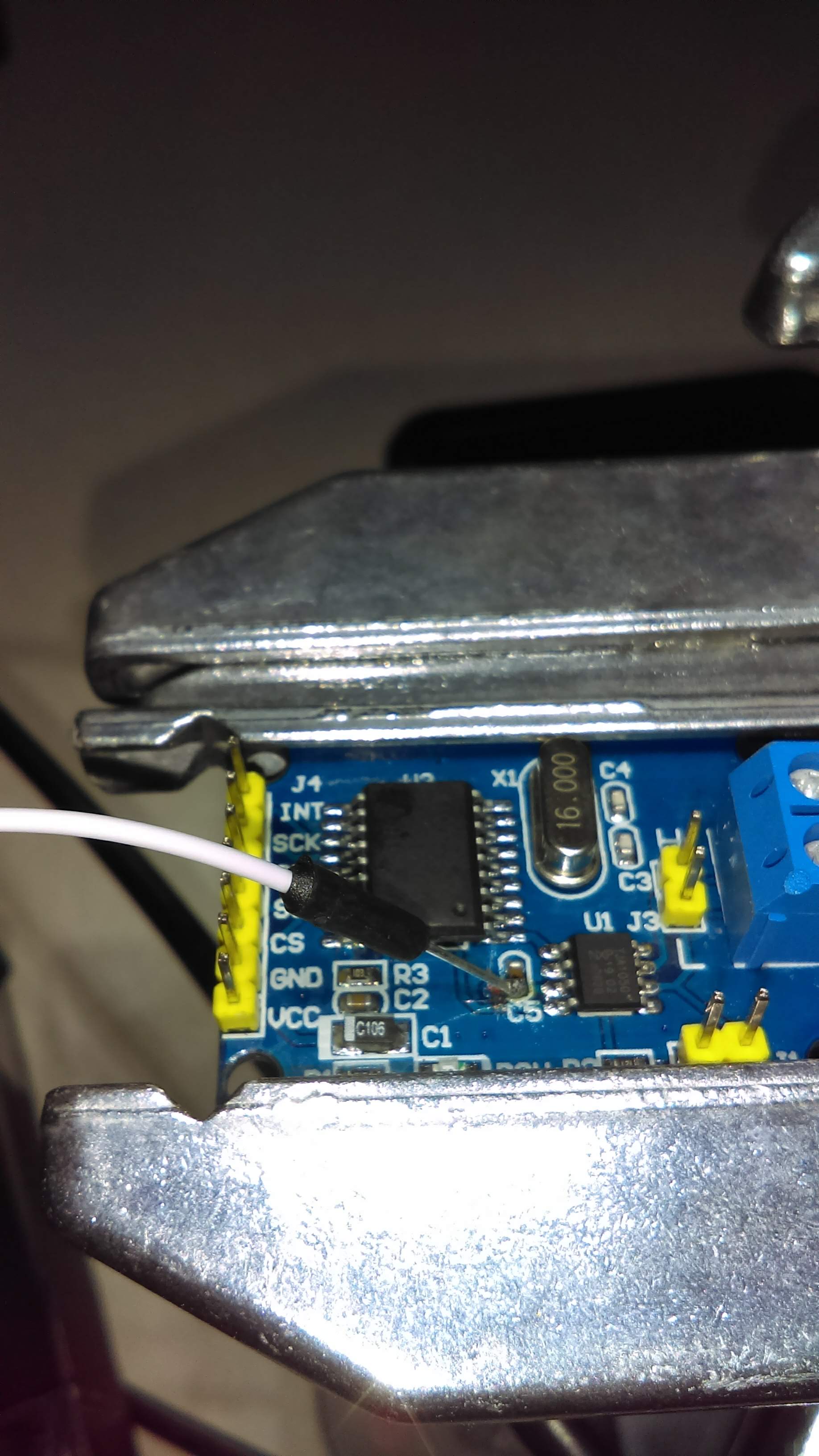
I purchased a breakout board and MCP2515 w/ TJA1050 transceiver from Ebay. I plan to cut the lead on the transceiver and wire my rx & tx directly to the M2-Breakout. Has anyone tried this? How were your results?

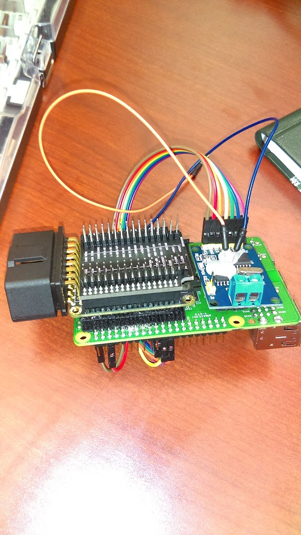
I want to use the Pi to write the CAN data either over-network or directly to an SD card. I do not have to use a Raspberry Pi for this project but have 2 available – Python is the largest necessity due to legacy applications. I’m more than happy to hear inputs and share my experience working through this!

I believe you are in uncharted waters with this. But as long as you connect to the proper wires on the M2 interface board you should find it will work. But not sure of the reason for using the M2 if you are purchasing a unit with everything already on it.

Using something like a PiCAN shield would seem more reasonable since it is already a done deal and will work with standard CANBUS utilities. To get it to work with the M2 for just CAN sounds like lots of work to accomplish what is already out there. The PiCAN shield is not the only one out there for the RPI either. I have a PiCAN and a CarBerry and both of those devices work great on my RPi 2b and 3. The CarBerry uses a proprietary interface but also supports SWCAN and LIN.

While the M2 is a nice little device with lots of cool features it really is not the best option for your project.

Okay, that’s perfect. I’ll work on that today and share my results.

The goal is to collect CAN data from a variety of vehicles, so the small form-factor and integrated OBD-II connector made the M2 desirable. I didn’t realize before tinkering that it only had a transceiver on board (but wondered if I could hack the MCP2515 used for SWCAN to support CAN0? Maybe another day).

I like the M2 for this application and hope I can get it to work. By going a straight Pi/shield route it looks like I’ll be buying more parts or soldering an OBD-II connector.

My other option was by-passing the breakout for CAN0 and CAN1. I’ll cut the transceiver lead and go that route first, but I think it would work if I solder directly to the pins on the breakout’s OBD pins. Thanks for the info, I’ll be sure to share my experience.

I’m planning to try this on my test-bed before a live vehicle over the weekend. I clipped the connection behind my MCP2515 and it’s transceiver. Then I soldered a wire to feed 5v to the capacitor and promptly accidentally knocked the capacitor off the board. So – the connection the transceiver now is completely messed up and I bought a handful of MCP2515 boards from aliexpress (around $1/ea) in case this doesn’t work.

(this was before breaking it)

I directly soldered leads onto the rx & tx pins on the MCP2515 chip next and bathed in hot glue so they don’t come undone. With some epoxy and velcro I made it modular. I found this guide on pinning the MCP2515 to the SPI ports on the pi: https://vimtut0r.com/2017/01/17/can-bus-with-raspberry-pi-howtoquickstart-mcp2515-kernel-4-4-x/ Obviously I skipped the 5v stuff with the TJA chip because I broke the capacitor.

All is wired and attached now. I need to make some headers for the M2 Breakout Board to interface with the Pi and I will report back on my experience. I should be able to provide adequate power from the OBD2 port to run everything.

A little larger than I hoped, but still more modular than a laptop/cable/controller. If this works I may print a modular case instead of using velcro and exposed wiring.

That’s some mad scientist looking hardware. Love it. This might be answered above, but could the M2 plus Pocket Beagle we are launching soon work for what you are trying to accomplish with the RasPi?

Very possibly! I headed on vacation and haven’t had a chance to test my creation yet. Is there a way to get my hands on one of those limited release copies?

One gripe I have with the rpi is it only supports one bus. I’ve never used a beaglebone, but some colleagues mentioned it might be better suited for this anyway. I will still forge forward with this build out of curiosity, but I’m very interested in the new product!

If there’s anyway to be a guinea pig please let me know.

There is always an extra board for motivated guinea pigs. I’ll see what we have.

I’ve been working on this project today and borrowed a Beagle Bone Black from a colleague to get some ideas. I’ve had some issues getting the M2 to send voltage. It draws power from pin 16 on the OBD, which supplies 12v. When I measure the voltage from 12v-out on the breakout board it reads ~2.5v and I get 0 on the 5v out. Has anyone had luck using the M2 to power another peripheral via OBD?

If anyone’s still reading, I mostly gave up on this project. It turned out to be way easier just to mount an OBD cable on a Raspberry Pi and use my controller/transceiver with that. For some reason I’ve not been able to get the M2 breakout board to properly divert voltage to get things running. If I ever revisit I will update!