Engine Swap - GM LS3 in Porsche 996

I recently did an engine swap on my 2002 Porsche 911 Carrera (996) with an LS3 from a Pontiac G8 (modded to be basically a Corvette engine).

I’m using the GM E38 ECU to run the engine and the Porsche ECU for everything else. I wired an OBD2 port for each ECU in the front of the car. I have the Under the Hood M2 and want to wire two OBD2 plugs to it.

I’m having some errors, so my first project is to data log from both ECUs at the same time for the past minute when I press a button. Then I would like to clear the CEL on the Porsche ECU. Eventually, I would like to read data from the GM ECU, modify it, and feed it to the Porsche ECU so it doesn’t know the engine is missing.

The GM OBD2 uses GM High Speed LAN Serial Data Bus + on Pin 6 and GM High Speed LAN Serial Data Bus - on Pin 14.

The Porsche ECU has the pins wired as shown in the picture below:
Capture

Pins 1, 4, 5, and 16 are shared between both ports, they are the power and ground wires. I think if I use some diodes and I can wire both ports to work independent or at the same time. So I think I can figure out the wiring.

I really need help with programming. That is something I have only dabbled with here and there over the years. Which libraries would work best for this?

My biggest problem is the water temp gauge gets an error. I need to record temps to find what is confusing the Porsche computer. Then I’ll figure out how to fake whatever sensors are most suspect and see if that fixes the problem.

I want to record data to an SD card. I need that data to be stored in a one minute buffer that records over the old data until I press a button, at which point it saves that minute buffer to the SD card. Finally, I need to know how to erase diagnostic codes like an OBD2 scanner does, maybe also turn off the Porsche ECU with the GM ECU keeping the engine running. That way when I press a button, it records the data from the last minute to find what went wrong, and then clears the codes so the gauge will work again. I plan to press the button whenever the gauge has the fault.

Any advice or help would be appreciated!

Do you know what the Porsche uses? As it is a 2002 it is a pre canbus vehicle.

You MAY find that you want to use 2 M2’s with their times synced to compare. Not 100% certain but that looks like it may be the case.

The Porsche is a CANBUS system. It was the first year they used it. The ECU, stability control, gauge cluster, and I think I few other modules use CANBUS to communicate.

Pins 3 and 7 are labeled “K LEAD”, so I am thinking that is “9141_K_BUS”?

Not sure, but I know the Porsche scanner tool and similar aftermarket units can talk to all the modules through the OBD2 port.

I was hoping the M2 could use all the different protocols at the same time. If it can, then I can use one M2 to talk to both ECUs. If not, then I would like to just record data from the Porsche ECU for now.

Thanks for your comment!

Well if it does indeed have Canbus then you likely are good to go. Since the M2 does have 2 canbus ports you could go that route. Although I don’t know how well it will work with 2 ports at the same time. If you find the M2 is challenged to do more than one channel at the same time you could use multiple M2’s or something like a PiCAN which is RPI based or a Carberry which is also RPI based. Both of those devices can be purchased with dual ports.

If you have a canbus and a lin or k-lin bus then I would concentrate on the canbus since the LIN/K-line would be more likely related to comfort items such as power windows, radio, hvac etc.

I’d like to butt in to say that pre-2008 European cars can most certainly use CAN. Bosch came out with CAN in 1985 for use with their ECU and fuel management systems. So, it can exist even that far back in the engine compartment of European cars, I have Mercedes that were CAN controlled all of the way back into the early 90’s. But, it is likely that such cars will only have CAN between engine control systems and not into the rest of the car. Mercedes was famous for using their own custom built diagnostics platform during this era.

But, what the OP said seems to suggest that both systems really use something other than CAN for comm. The M2 can still handle such things but I think the state of support is lagging at least a little for the other bus types.

Yup! Mercedes was wayyyy ahead of the times.

Im pretty sure the W140 S-class was the first car in the world to use a true CAN bus for interconnecting and sharing real time data between multiple ECU’s.

I really wish I could find an early-90’s W140 benz to sniff the bus…im extremely curious to see what kind of traffic existed/how fast the messages were broadcast/how much is going on in a (designed in) late-80’s CAN bus. It was literally space age at the time and never seen before…fast forward to 2017 and friggin lawn mowers have CAN!

I think I have the wiring figured out. I am going to use the M2 to log data through both OBD2 ports as planned. I will wire in two buttons, one to log the last minute of data to the SD card, and another to clear the codes on the Porsche ECU.

I also realized that my coolant temp gauge error is likely from not having all the temp sensors hooked up.

I decided to buy an Arduino Nano to wire into the Porsche ECU under the back seat. It will get the coolant temp from the M2 and ambient temp from the engine compartment temp sensor, that is mounted under the back seat.

I will use that information to calculate a reasonable temp sensor signal for the intake air temp, and oil temp. I will also modify the engine compartment temp when the engine compartment fan signal is on, to make the ECU thinks the fan is still there and working.

If anyone sees any errors in my wiring, please point them out. I’m going to try to wire and mount everything in the car this weekend.

I’m still somewhat lost on the software end. I’ll just have to see what I can do.

Got the OBD2 ports wired! Finally got SavvyCAN to work!

I’m not sure how to interpret the data. I think I need a database file? Is the one for GM yet?

Your best bet is to find some information that explains how the CANBUS works. Do you have a copy of the Car Hackers Handbook?

Once you understand how the command structure is setup you can go from there. You need to figure out the module id’s for each module and then sort out what they do from the data you are seeing.

Depending on what you want to do you should be able to use the M2 as a bridge between the two systems.

I gave up on the SavvyCAN for now. I’m trying to use the OBD9141 library instead, based on the MPG example.

I’ve changed it to read VSS and turn on more LEDs the faster you go.

I can’t get it to initialized and I’m not sure why. There seems to be a OBD9141_DEBUG function, but I don’t know how to display it in the serial console.

Here is my code:


/*   
 *  VSS LED display using Adafruit NeoPixel and Macchina M2 with a pre-CAN bus 
 *  ISO9141 (K-line) based vehicle.
 *  
 *  These parts are used in this project:
 *  
 *  https://www.macchina.cc/content/m2-under-dash
 *  https://www.adafruit.com/product/2869
 *
 *  Requires "Macchina M2" board to be installed and selected. For instructions, go here: 
 *  http://docs.macchina.cc/m2/getting-started/arduino.html
 *  
 *  This sketch requires the following libraries:
 *  
 *  https://github.com/iwanders/OBD9141
 *  https://github.com/adafruit/Adafruit_NeoPixel
 *  
*/
#include <Arduino.h>
#include <pins_arduino.h>
#include <stdint.h>

#include "OBD9141.h"

// The RX pin of the Serial1 connected to 9141 K RX of tranciever.
#define RX_PIN 8

// The Tx pin of the Serial1 connected to 9141 K TX of tranciever.
#define TX_PIN 22

#define OBD9141_DEBUG

OBD9141 obd;

int VSS = 0;

void setup() {
   
// initialize digital pin DS2 as an output. RED LED
  pinMode(DS2, OUTPUT);
  
// initialize digital pin DS3 as an output. YELLOW LED
  pinMode(DS3, OUTPUT); 
    
// initialize digital pin DS4 as an output. YELLOW LED
  pinMode(DS4, OUTPUT);
  
// initialize digital pin DS5 as an output. YELLOW LED
  pinMode(DS5, OUTPUT);
  
// initialize digital pin DS6 as an output. GREEN LED
  pinMode(DS6, OUTPUT);
  
  SerialUSB.begin(115200);
  delay(2000);

  pinMode(PS_J1850_9141, OUTPUT);
  digitalWrite(PS_J1850_9141, HIGH);

  obd.begin(Serial1, RX_PIN, TX_PIN);

}

void loop() {
  SerialUSB.println("Looping");

  // obd.set_port(false);
  bool init_success =  obd.init();
  SerialUSB.print("init_success:");
  SerialUSB.println(init_success);

  init_success = true;
  // Uncomment this line if you use the simulator to force the init to be
  // interpreted as successful. With an actual ECU; be sure that the init is
  // succesful before trying to request PID's.

  if (init_success) {

    bool res = true;
    while (res) {

      res = obd.getCurrentPID(0x0D, 1);
      
      if (res) {
        SerialUSB.print("Result 0x0D (speed): ");
        SerialUSB.println(obd.readUint8());
        VSS = int((obd.readUint8()));
        SerialUSB.println(VSS);
      }

      delay(50);                           

      SerialUSB.println("VSS");
      SerialUSB.println(VSS);
      SerialUSB.println();

      for ( int i = 0; i < 8; i++ ) {       // turn them all off
        digitalWrite(DS2, HIGH);  // turn the LED off by making the voltage HIGH
        digitalWrite(DS3, HIGH);  // turn the LED off by making the voltage HIGH
        digitalWrite(DS4, HIGH);  // turn the LED off by making the voltage HIGH
        digitalWrite(DS5, HIGH);  // turn the LED off by making the voltage HIGH
        digitalWrite(DS6, HIGH);  // turn the LED off by making the voltage HIGH

      }

      if (VSS > 40) { // GREEN LED ON, Leave others on
        digitalWrite(DS2, LOW);  // turn the LED on by making the voltage LOW
        digitalWrite(DS3, LOW);  // turn the LED on by making the voltage LOW
        digitalWrite(DS4, LOW);  // turn the LED on by making the voltage LOW
        digitalWrite(DS5, LOW);  // turn the LED on by making the voltage LOW
        digitalWrite(DS6, LOW);  // turn the LED on by making the voltage LOW
      }

      if (30 < VSS <= 40) {  // THREE YELLOW LED AND RED ON
        digitalWrite(DS2, LOW);  // turn the LED on by making the voltage LOW
        digitalWrite(DS3, LOW);  // turn the LED on by making the voltage LOW
        digitalWrite(DS4, LOW);  // turn the LED on by making the voltage LOW
        digitalWrite(DS5, LOW);  // turn the LED on by making the voltage LOW
        digitalWrite(DS6, HIGH);  // turn the LED off by making the voltage HIGH
      }
      if (20 < VSS <= 30) {  // THREE YELLOW LED AND RED ON
        digitalWrite(DS2, LOW);  // turn the LED on by making the voltage LOW
        digitalWrite(DS3, LOW);  // turn the LED on by making the voltage LOW
        digitalWrite(DS4, LOW);  // turn the LED on by making the voltage LOW
        digitalWrite(DS5, HIGH);  // turn the LED off by making the voltage HIGH
        digitalWrite(DS6, HIGH);  // turn the LED off by making the voltage HIGH
      }
      if (10 < VSS <= 20) {  // THREE YELLOW LED AND RED ON
        digitalWrite(DS2, LOW);  // turn the LED on by making the voltage LOW
        digitalWrite(DS3, LOW);  // turn the LED on by making the voltage LOW
        digitalWrite(DS4, HIGH);  // turn the LED off by making the voltage HIGH
        digitalWrite(DS5, HIGH);  // turn the LED off by making the voltage HIGH
        digitalWrite(DS6, HIGH);  // turn the LED off by making the voltage HIGH
      }
      if (VSS <= 10) {  // THREE YELLOW LED AND RED ON
        digitalWrite(DS2, LOW);  // turn the LED on by making the voltage LOW
        digitalWrite(DS3, HIGH);  // turn the LED off by making the voltage HIGH
        digitalWrite(DS4, HIGH);  // turn the LED off by making the voltage HIGH
        digitalWrite(DS5, HIGH);  // turn the LED off by making the voltage HIGH
        digitalWrite(DS6, HIGH);  // turn the LED off by making the voltage HIGH
      }
    }
  }
}

I figured out that the Porsche OBD pin 3 should be hooked up to pin 21, because it is a K-Line for all the non engine modules. Not sure if I will be able to communicate with it later, but at least it will be wired correctly.

OBD pin 7 is the engine K-Line and I already have that hooked up to pin 22, which is the K-Line bus. I have made some corrections to my sketch to match the MPG example.

#include <Arduino.h>
#include <pins_arduino.h>
#include <stdint.h>

#include "OBD9141.h"

// The RX pin of the Serial1 connected to 9141 K RX of tranciever.
#define RX_PIN LIN_KRX

// The Tx pin of the Serial1 connected to 9141 K TX of tranciever.
#define TX_PIN LIN_KTX

// The Enable pin connected to 9141 SLP pin of tranciever.
#define EN_PIN LIN_KSLP

#define OBD9141_DEBUG

OBD9141 obd;

int VSS = 0;

void setup() {
   
// initialize digital pin DS2 as an output. RED LED
  pinMode(DS2, OUTPUT);
  
// initialize digital pin DS3 as an output. YELLOW LED
  pinMode(DS3, OUTPUT); 
    
// initialize digital pin DS4 as an output. YELLOW LED
  pinMode(DS4, OUTPUT);
  
// initialize digital pin DS5 as an output. YELLOW LED
  pinMode(DS5, OUTPUT);
  
// initialize digital pin DS6 as an output. GREEN LED
  pinMode(DS6, OUTPUT);
  
  SerialUSB.begin(115200);
  delay(2000);

  pinMode(EN_PIN, OUTPUT);
  digitalWrite(EN_PIN, HIGH);

  pinMode(PS_J1850_9141, OUTPUT);
  digitalWrite(PS_J1850_9141, HIGH);

  obd.begin(Serial1, RX_PIN, TX_PIN);

}

void loop() {
  SerialUSB.println("Looping");

  // obd.set_port(false);
  bool init_success =  obd.init();
  SerialUSB.print("init_success:");
  SerialUSB.println(init_success);

  //init_success = true;
  // Uncomment this line if you use the simulator to force the init to be
  // interpreted as successful. With an actual ECU; be sure that the init is
  // succesful before trying to request PID's.

  if (init_success) {

    bool res = true;
    while (res) {

      res = obd.getCurrentPID(0x0D, 1);
      
      if (res) {
        SerialUSB.print("Result 0x0D (speed): ");
        SerialUSB.println(obd.readUint8());
        VSS = int((obd.readUint8()));
        SerialUSB.println(VSS);
      }

      delay(50);                           

      for ( int i = 0; i < 8; i++ ) {       // turn them all off
        digitalWrite(DS2, HIGH);  // turn the LED off by making the voltage HIGH
        digitalWrite(DS3, HIGH);  // turn the LED off by making the voltage HIGH
        digitalWrite(DS4, HIGH);  // turn the LED off by making the voltage HIGH
        digitalWrite(DS5, HIGH);  // turn the LED off by making the voltage HIGH
        digitalWrite(DS6, HIGH);  // turn the LED off by making the voltage HIGH

      }

      if (VSS > 40) { // GREEN and all LED on
        digitalWrite(DS2, LOW);  // turn the LED on by making the voltage LOW
        digitalWrite(DS3, LOW);  // turn the LED on by making the voltage LOW
        digitalWrite(DS4, LOW);  // turn the LED on by making the voltage LOW
        digitalWrite(DS5, LOW);  // turn the LED on by making the voltage LOW
        digitalWrite(DS6, LOW);  // turn the LED on by making the voltage LOW
      }

      if (30 < VSS <= 40) {  // THREE YELLOW and RED LED on
        digitalWrite(DS2, LOW);  // turn the LED on by making the voltage LOW
        digitalWrite(DS3, LOW);  // turn the LED on by making the voltage LOW
        digitalWrite(DS4, LOW);  // turn the LED on by making the voltage LOW
        digitalWrite(DS5, LOW);  // turn the LED on by making the voltage LOW
        digitalWrite(DS6, HIGH);  // turn the LED off by making the voltage HIGH
      }
      if (20 < VSS <= 30) {  // TWO YELLOW and RED LED on
        digitalWrite(DS2, LOW);  // turn the LED on by making the voltage LOW
        digitalWrite(DS3, LOW);  // turn the LED on by making the voltage LOW
        digitalWrite(DS4, LOW);  // turn the LED on by making the voltage LOW
        digitalWrite(DS5, HIGH);  // turn the LED off by making the voltage HIGH
        digitalWrite(DS6, HIGH);  // turn the LED off by making the voltage HIGH
      }
      if (10 < VSS <= 20) {  // YELLOW and RED LED on
        digitalWrite(DS2, LOW);  // turn the LED on by making the voltage LOW
        digitalWrite(DS3, LOW);  // turn the LED on by making the voltage LOW
        digitalWrite(DS4, HIGH);  // turn the LED off by making the voltage HIGH
        digitalWrite(DS5, HIGH);  // turn the LED off by making the voltage HIGH
        digitalWrite(DS6, HIGH);  // turn the LED off by making the voltage HIGH
      }
      if (VSS <= 10) {  // RED LED on
        digitalWrite(DS2, LOW);  // turn the LED on by making the voltage LOW
        digitalWrite(DS3, HIGH);  // turn the LED off by making the voltage HIGH
        digitalWrite(DS4, HIGH);  // turn the LED off by making the voltage HIGH
        digitalWrite(DS5, HIGH);  // turn the LED off by making the voltage HIGH
        digitalWrite(DS6, HIGH);  // turn the LED off by making the voltage HIGH
      }
    }
  }
  delay(3000);
}

I am also unsure if I have the grounds wired correctly. Pin 4 and 5 of each OBD2 port are bridged together in the connectors, but I have both spliced together to the chassis ground, pin 12. I think I am going to separate pin 4 and 5 and wire pin 5 to a digital ground. Maybe the cleaner ground will help.

I think I might have some progress. Once I can get OBD PID data, I can start programming and wiring the rest of this.

Those changes got it to work. It connects to the ECU and outputs the speed to console. Only the red LED turns on though. My IF statements must be wrong.

EDIT: I realized my syntax for the IF statements was all wrong. Been a long time since I programmed. I think the code below would be correct instead.

if (VSS > 50) { // GREEN and all LED on
        digitalWrite(DS2, LOW);  // turn the LED on by making the voltage LOW
        digitalWrite(DS3, LOW);  // turn the LED on by making the voltage LOW
        digitalWrite(DS4, LOW);  // turn the LED on by making the voltage LOW
        digitalWrite(DS5, LOW);  // turn the LED on by making the voltage LOW
        digitalWrite(DS6, LOW);  // turn the LED on by making the voltage LOW
      }

      else if (VSS > 40 && VSS <=50) {  // THREE YELLOW and RED LED on
        digitalWrite(DS2, LOW);  // turn the LED on by making the voltage LOW
        digitalWrite(DS3, LOW);  // turn the LED on by making the voltage LOW
        digitalWrite(DS4, LOW);  // turn the LED on by making the voltage LOW
        digitalWrite(DS5, LOW);  // turn the LED on by making the voltage LOW
        digitalWrite(DS6, HIGH);  // turn the LED off by making the voltage HIGH
      }
      else if (VSS > 30 && VSS <=40) {  // TWO YELLOW and RED LED on
        digitalWrite(DS2, LOW);  // turn the LED on by making the voltage LOW
        digitalWrite(DS3, LOW);  // turn the LED on by making the voltage LOW
        digitalWrite(DS4, LOW);  // turn the LED on by making the voltage LOW
        digitalWrite(DS5, HIGH);  // turn the LED off by making the voltage HIGH
        digitalWrite(DS6, HIGH);  // turn the LED off by making the voltage HIGH
      }
      else if (VSS > 20 && VSS <=30) {  // YELLOW and RED LED on
        digitalWrite(DS2, LOW);  // turn the LED on by making the voltage LOW
        digitalWrite(DS3, LOW);  // turn the LED on by making the voltage LOW
        digitalWrite(DS4, HIGH);  // turn the LED off by making the voltage HIGH
        digitalWrite(DS5, HIGH);  // turn the LED off by making the voltage HIGH
        digitalWrite(DS6, HIGH);  // turn the LED off by making the voltage HIGH
      }
      else if (VSS > 10 && VSS <=20) {  // RED LED on
        digitalWrite(DS2, LOW);  // turn the LED on by making the voltage LOW
        digitalWrite(DS3, HIGH);  // turn the LED off by making the voltage HIGH
        digitalWrite(DS4, HIGH);  // turn the LED off by making the voltage HIGH
        digitalWrite(DS5, HIGH);  // turn the LED off by making the voltage HIGH
        digitalWrite(DS6, HIGH);  // turn the LED off by making the voltage HIGH
      }
      else {
        digitalWrite(DS2, HIGH);  // turn the LED off by making the voltage HIGH
        digitalWrite(DS3, HIGH);  // turn the LED off by making the voltage HIGH
        digitalWrite(DS4, HIGH);  // turn the LED off by making the voltage HIGH
        digitalWrite(DS5, HIGH);  // turn the LED off by making the voltage HIGH
        digitalWrite(DS6, HIGH);  // turn the LED off by making the voltage HIGH
      }

Oh man, this is sweet. What happens when you hit 88 MPH? Let’s see a video!

Thanks! The car is awesome! I’m still editing a video or two, should have them ready soon.

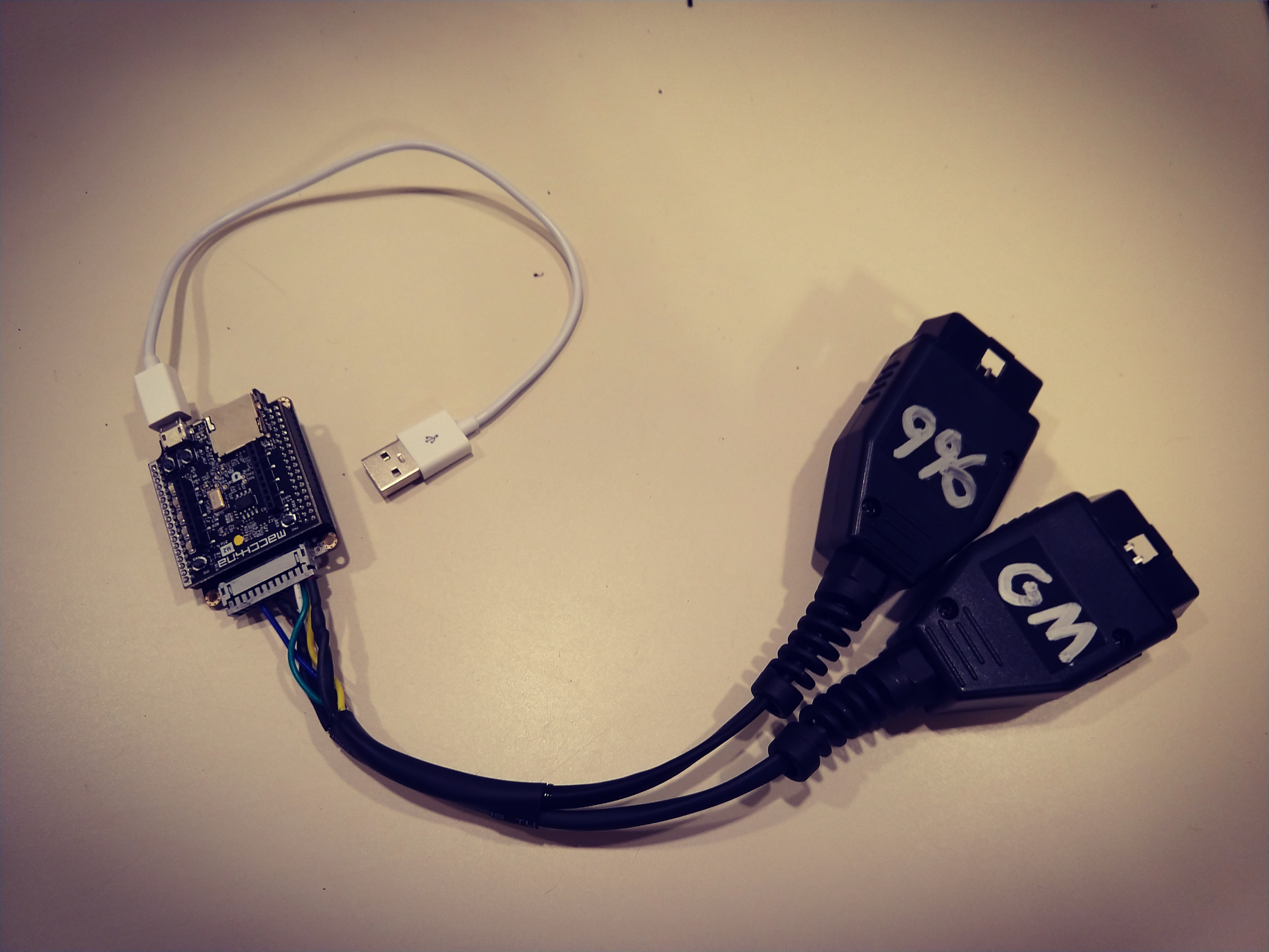
Pretty much the whole build is on my Instagram @stowellandrew

Anyway, I got it to record a few PIDs and save them to an SD card, but I’m having formatting issues. Here is my code and I’m trying to get CSV file I can import into Excel.

// Including Arduino_Due_SD_HSCMI library also creates SD object (MassStorage class)
#include <Arduino_Due_SD_HSMCI.h> // This creates the object SD#include <Arduino.h>
#include <pins_arduino.h>
#include <stdint.h>

#include "OBD9141.h"

// The RX pin of the Serial1 connected to 9141 K RX of tranciever.
#define RX_PIN LIN_KRX

// The Tx pin of the Serial1 connected to 9141 K TX of tranciever.
#define TX_PIN LIN_KTX

// The Enable pin connected to 9141 SLP pin of tranciever.
#define EN_PIN LIN_KSLP

#define OBD9141_DEBUG

OBD9141 obd;

// We need to create FileStore object, we will be using it to open/create file and to close file.
FileStore FS;

// Variables
unsigned int i=0;

//int runtime = 0;
int VSS = 0;
int RPM = 0;
float ECT = 0;
float IAT = 0;
//int airtemp = 0;
//int oiltemp = 0;

void setup() {
   
  // initialize digital pin DS2 as an output. RED LED
  pinMode(DS2, OUTPUT);
  
  // initialize digital pin DS3 as an output. YELLOW LED
  pinMode(DS3, OUTPUT); 
    
  // initialize digital pin DS4 as an output. YELLOW LED
  pinMode(DS4, OUTPUT);
  
  // initialize digital pin DS5 as an output. YELLOW LED
  pinMode(DS5, OUTPUT);
  
  // initialize digital pin DS6 as an output. GREEN LED
  pinMode(DS6, OUTPUT);
  
  SerialUSB.begin(115200);
  delay(2000);

  pinMode(EN_PIN, OUTPUT);
  digitalWrite(EN_PIN, HIGH);

  pinMode(PS_J1850_9141, OUTPUT);
  digitalWrite(PS_J1850_9141, HIGH);

  obd.begin(Serial1, RX_PIN, TX_PIN);

  // Check if there is card inserted
  SD.Init(); // Initialization of HSCMI protocol and SD socket switch GPIO (to adjust pin number go to library source file - check Getting Started Guide)
  FS.Init(); // Initialization of FileStore object for file manipulation

  /* Following code creates file "data.csv" in dir "0:" for logging raw data. Every time pushbutton is pushed, counter increment for 1 and number is logged into "data.csv".
   Check Getting Started Guide for Debug options (Debug is enabled by default). 

   CAUTION!
   Code only works if there is no directory or file with the same name. Code first checks if name is alredy used when is needed. */

  char message[] = "Line,RPM,MPH,ECT,IAT\n"; // Message at the beginnign of the file
  
  // Create/Open file "data.csv"
  FS.CreateNew("0:","data.csv"); // Create new file, if alredy exists it will be overwritten
  //FS.GoToEnd(); // Do not need when creating file because new file is opened and position 0
  FS.Write(message); // writing message
  FS.Close(); // we need to close file to store all the data that was written to it
   
}

void loop() {
  SerialUSB.println("Looping");

  // obd.set_port(false);
  bool init_success =  obd.init();
  SerialUSB.print("init_success:");
  SerialUSB.println(init_success);

  //init_success = true;
  // Uncomment this line if you use the simulator to force the init to be
  // interpreted as successful. With an actual ECU; be sure that the init is
  // succesful before trying to request PID's.

  if (init_success) {

    bool res = true;
    while (res) {

      //res = obd.getCurrentPID(0x1F, 2);

      //if (res){
        //SerialUSB.print("Result 0x0C (Engine Run Time): ");
        //SerialUSB.println(obd.readUint16()/4);
        //runtime = (obd.readUint16()/4);
      //}

      res = obd.getCurrentPID(0x0C, 2);

      if (res){
        SerialUSB.print("Result 0x0C (RPM): ");
        SerialUSB.println(obd.readUint16()/4);
        RPM = (obd.readUint16()/4);
      }

      res = obd.getCurrentPID(0x0D, 1);
      
      if (res) {
        SerialUSB.print("Result 0x0D (Speed MPH): ");
        SerialUSB.println(obd.readUint8());
        VSS = (obd.readUint8());
      }

      res = obd.getCurrentPID(0x05, 1);

      if (res){
        SerialUSB.print("Result 0x05 (ECT C): ");
        ECT = (obd.readUint8()) - 40 ;
        SerialUSB.println(ECT);
      }

      res = obd.getCurrentPID(0x0F, 1);

      if (res){
        SerialUSB.print("Result 0x05 (IAT C): ");
        IAT = (obd.readUint8()) - 40 ;
        SerialUSB.println(IAT);
      }

      //res = obd.getCurrentPID(0x46, 1);

      //if (res){
        //SerialUSB.print("Result 0x46 (Ambient): ");
        //SerialUSB.println(obd.readUint8());
        //airtemp = (obd.readUint8());
      //}

      //res = obd.getCurrentPID(0x5C, 1);

      //if (res){
        //SerialUSB.print("Result 0x5C (Oil Temp): ");
        //SerialUSB.println(obd.readUint8());
        //oiltemp = (obd.readUint8());
      //}

      if (RPM > 4000) { // GREEN and all LED on
        digitalWrite(DS2, LOW);  // turn the LED on by making the voltage LOW
        digitalWrite(DS3, LOW);  // turn the LED on by making the voltage LOW
        digitalWrite(DS4, LOW);  // turn the LED on by making the voltage LOW
        digitalWrite(DS5, LOW);  // turn the LED on by making the voltage LOW
        digitalWrite(DS6, LOW);  // turn the LED on by making the voltage LOW
      }

      else if (RPM > 3000 && RPM <=4000) {  // THREE YELLOW and GREEN LED on
        digitalWrite(DS2, HIGH);  // turn the LED off by making the voltage HIGH
        digitalWrite(DS3, LOW);  // turn the LED on by making the voltage LOW
        digitalWrite(DS4, LOW);  // turn the LED on by making the voltage LOW
        digitalWrite(DS5, LOW);  // turn the LED on by making the voltage LOW
        digitalWrite(DS6, LOW);  // turn the LED on by making the voltage LOW
      }
      else if (RPM > 2000 && RPM <=3000) {  // TWO YELLOW and GREEN LED on
        digitalWrite(DS2, HIGH);  // turn the LED on by making the voltage LOW
        digitalWrite(DS3, HIGH);  // turn the LED on by making the voltage LOW
        digitalWrite(DS4, LOW);  // turn the LED on by making the voltage LOW
        digitalWrite(DS5, LOW);  // turn the LED off by making the voltage HIGH
        digitalWrite(DS6, LOW);  // turn the LED off by making the voltage HIGH
      }
      else if (RPM > 1000 && RPM <=2000) {  // YELLOW and RED LED on
        digitalWrite(DS2, HIGH);  // turn the LED on by making the voltage LOW
        digitalWrite(DS3, HIGH);  // turn the LED on by making the voltage LOW
        digitalWrite(DS4, HIGH);  // turn the LED off by making the voltage HIGH
        digitalWrite(DS5, LOW);  // turn the LED off by making the voltage HIGH
        digitalWrite(DS6, LOW);  // turn the LED off by making the voltage HIGH
      }
      else if (RPM > 100 && RPM <=1000) {  // RED LED on
        digitalWrite(DS2, HIGH);  // turn the LED on by making the voltage LOW
        digitalWrite(DS3, HIGH);  // turn the LED off by making the voltage HIGH
        digitalWrite(DS4, HIGH);  // turn the LED off by making the voltage HIGH
        digitalWrite(DS5, HIGH);  // turn the LED off by making the voltage HIGH
        digitalWrite(DS6, LOW);  // turn the LED off by making the voltage HIGH
      }
      else {
        digitalWrite(DS2, HIGH);  // turn the LED off by making the voltage HIGH
        digitalWrite(DS3, HIGH);  // turn the LED off by making the voltage HIGH
        digitalWrite(DS4, HIGH);  // turn the LED off by making the voltage HIGH
        digitalWrite(DS5, HIGH);  // turn the LED off by making the voltage HIGH
        digitalWrite(DS6, HIGH);  // turn the LED off by making the voltage HIGH
      }
      if (RPM > 100) {
        // Increment counter
        i++;
        // Preapre buffer, write() method is accepting only array of chars, it is easier for us to create a string and then transform it into array of chars
        String str = String(i) + "," + String(RPM) + "," + String(VSS) + "," + String(ECT,1) + "," + String(IAT,1); // creates a string
        char write_buffer[sizeof(str)]; // Creating array of char in length of our string
        str.toCharArray(write_buffer,sizeof(str)); // transform string to array of chars of strings's size
        // SerialUSB.print(write_buffer); // We can check what was created, SerialUSB.print(.) uses serial buffer so we can print string or array of chars 
        // Write data to file.
        FS.Open("0:","data.csv",true); // openning file
        FS.GoToEnd(); // Search for the end of file and write to it
        FS.Write(write_buffer); // write data to file
        FS.Write("\n"); // new line
        FS.Close(); // to save data in file, we must close the file
      }
    }
  delay(250);
  }
  VSS = 0;
  RPM = 0;
  ECT = 0;
  IAT = 0;
}

And here is the file I get:

Line,RPM,MPH,ECT,IAT
1,952,0,39.
2,917,0,39.
3,894,0,39.
4,899,0,39.
5,906,0,39.
6,887,0,39.
7,916,0,39.
8,933,0,39.
9,938,0,39.
10,914,0,39
11,895,0,39
12,871,0,39
13,875,0,39
14,941,0,39
15,949,0,39
16,1078,0,3
17,1291,0,3
18,1482,0,3
19,1590,0,3
20,1667,0,3
21,1451,0,3
22,1181,0,3
23,1086,0,3
24,1004,0,3
25,926,0,39
26,890,0,39
27,924,0,39
28,926,0,39
29,915,0,39
30,905,0,39
31,900,0,39
32,953,0,39
33,1310,0,3
34,1582,0,3
35,1738,0,3
36,1691,0,3
37,1407,0,3
38,1247,0,3
39,1100,0,3
40,967,0,38
41,915,0,38
42,885,0,38
43,900,0,38
44,921,0,38
45,898,0,38
46,876,0,38
47,892,0,38
48,912,0,38
49,910,0,38
50,903,0,38
51,918,0,37
52,921,0,38
53,901,0,37
54,913,0,37
55,883,0,37
56,873,0,37
57,902,0,37
58,904,0,37
59,874,0,37
60,874,0,37
61,885,0,37
62,880,0,37
63,878,0,37
64,827,0,37
65,845,0,37
66,893,0,37
67,917,0,37
68,860,0,37
69,868,0,37
70,872,0,37
71,853,0,37
72,817,0,37
73,830,0,37
74,845,0,37
75,829,0,37
76,851,0,37
77,882,0,37
78,846,0,37
79,861,0,37
80,859,0,37
81,862,0,37
82,862,0,37
83,825,0,37
84,811,0,37
85,853,0,37
86,837,0,37
87,826,0,37
88,873,0,37
89,825,0,37
90,849,0,37
91,822,0,38
92,836,0,37
93,812,0,38
94,835,0,38
95,838,0,38
96,859,0,38
97,849,0,38
98,834,0,38
99,833,0,38
100,839,0,3
101,859,0,3
102,824,0,3
103,837,0,3
104,831,0,3
105,849,0,3
106,841,0,3
107,858,0,3
108,845,0,3
109,827,0,3
110,827,0,3
111,802,0,3
112,822,0,3
113,841,0,3
114,836,0,3
115,834,0,3
116,860,0,3
117,813,0,3
118,818,0,3
119,834,0,3
120,830,0,3
121,849,0,3
122,836,0,3
123,827,0,3
124,852,0,3
125,814,0,3
126,809,0,3
127,787,0,3
128,821,0,3
129,828,0,3
130,835,0,3
131,816,0,3
132,786,0,3
133,828,0,3
134,850,0,3
135,828,0,3
136,847,0,3
137,808,0,3
138,804,0,3
139,786,0,3
140,819,0,3
141,831,0,4
142,809,0,4
143,785,0,4
144,787,0,4
145,769,0,4
146,784,0,4
147,781,0,4
148,819,0,4
149,786,0,4
150,766,0,4
151,837,0,4
152,759,0,4
153,802,0,4
154,775,0,4
155,803,0,4
156,818,0,4
157,808,0,4
158,757,0,4
159,789,0,4
160,839,0,4
161,810,0,4
162,790,0,4
163,792,0,4
164,783,0,4
165,812,0,4
166,813,0,4
167,806,0,4
168,761,0,4
169,774,0,4
170,802,0,4
171,757,0,4
172,793,0,4
173,745,0,4
174,775,0,4
175,770,0,4
176,793,0,4
177,792,0,4
178,776,0,4
179,781,0,4
180,789,0,4
181,785,0,4
182,774,0,4
183,784,0,4
184,785,0,4
185,731,0,4
186,774,0,4
187,1005,0,
188,1893,0,
189,1822,0,
190,1529,0,
191,1293,0,
192,1197,0,
193,1109,0,
194,1021,0,
195,926,0,4
196,880,0,4
197,870,0,4
198,872,0,4
199,1006,0,
200,1544,0,
201,1958,0,
202,2086,0,
203,1726,0,
204,1478,0,
205,1346,0,
206,1233,0,
207,1124,0,
208,989,0,4
209,944,0,4
210,904,0,4
211,866,0,4
212,874,0,4
213,856,0,4
214,862,0,4
215,877,0,4
216,859,0,4
217,891,0,4
218,888,0,4
219,876,0,4
220,900,0,4
221,888,0,4
222,837,0,4
223,845,0,4
224,812,0,4
225,801,0,4
226,836,0,4
227,826,0,4
228,822,0,4
229,814,0,4
230,795,0,4
231,833,0,4
232,826,0,4
233,804,0,4
234,823,0,4
235,836,0,4
236,817,0,4
237,817,0,4
238,786,0,4
239,801,0,4
240,775,0,4
241,481,0,4
242,211,0,4
243,105,0,4

It looks like it is getting truncated too soon?