
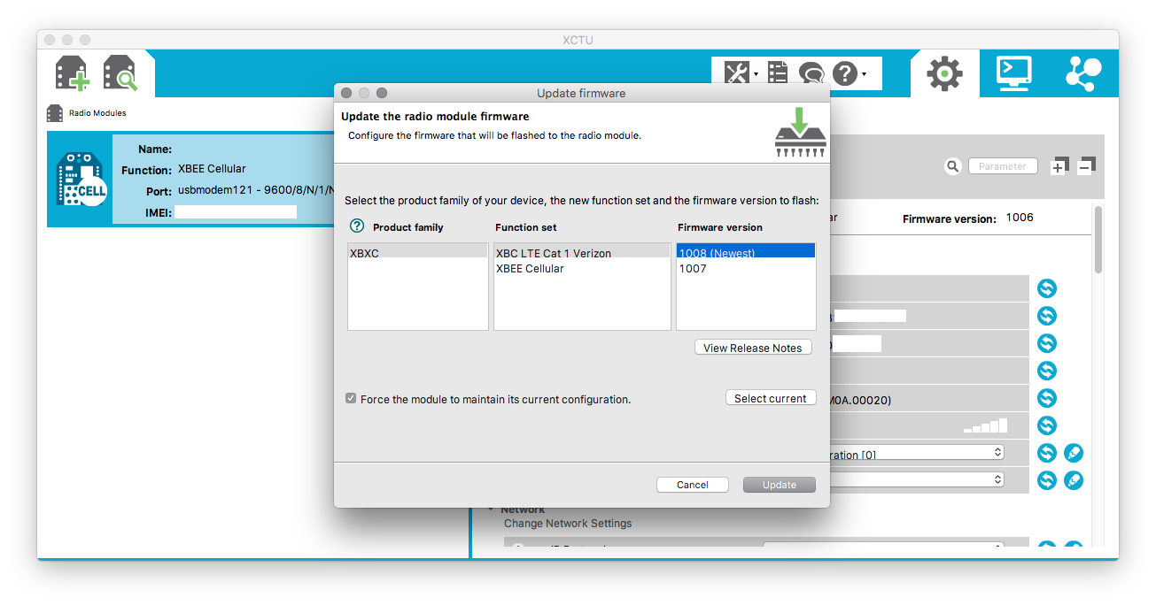
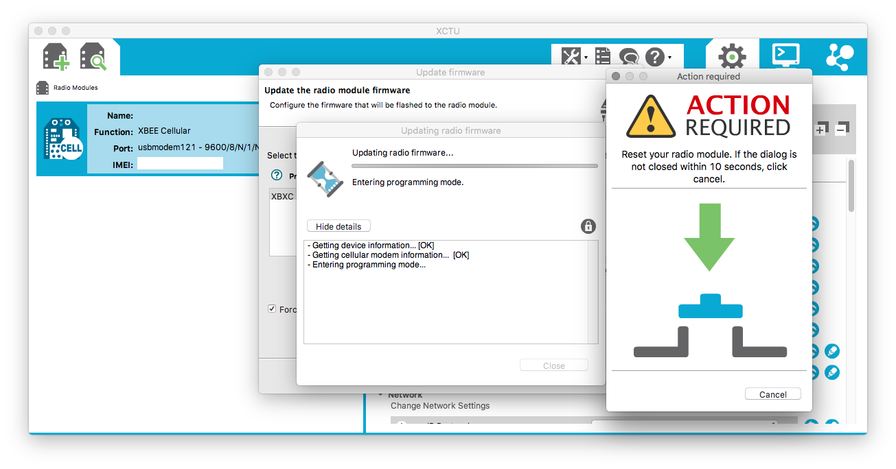
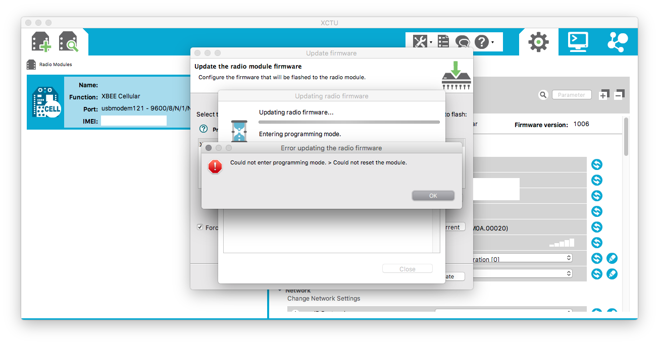
Anyone know how to update the cell modem firmware? I am using the XCTU software from Digi and am able to read the configuration but when I try to upload the firmware I get a message asking to push the reset button on the modem. There’s no reset although the Digi Documentation says PIN 5 is the reset pin. No luck bridging that to the ground (PIN 10) either though. Anyone have thoughts? This occurs with both the XBC LTE Cat 1 Verizon AND the XBEE Cellular Function sets.
1 Like
Sorry for the multiple posts. System will not let me post multiple screenshots in a single reply. 
I suspect the issue here is that upgrading the XBEE modem requires the flow control signals (RTS, CTS, DTR). I know that DIGI’s Developer board (XBIB-U-DEV) will let you update the FW. The schematic shows nothing really special going on with the RESET line, but does show the flow control lines connected.
To get this to work, we’ll need to write some code to make M2’s processor act as a serial converter. This will be similar to the serial port forwarding found here but with the flow control signals being controlled. Here are those pins on M2 socket:
http://docs.macchina.cc/m2/technical-references/pin-mapping.html#xbee
XB_MULT1 is DTR
XBEE_CTS is CTS
XBEE_RTS is RTS
Pinout of XBEE Cellular LTE module:
A quick search for existing projects that may prove useful:
Here is a project that works with Arduino Leonardo apparently:
http://www.stderr.nl/Blog/Hardware/Electronics/Arduino/XBee/XctuAndArduino.html
And some code:
@nickganga or anyone else want to give this project a shot?
1 Like
@josh, this is my first time delving into Arduino so anyone who can offer some assistance would be welcome!
Quick update on this project:
Just to better understand how these modems actually go into program mode, I did a little trial and error to see what the minimum connections would be but still be able to update the firmware.
I disconnected every pin between the “DIGI Developer board” and the modem EXCEPT for:
Pins 1 (+3.3V) 2 (RX), 3 (TX), 9 (DTR) and 10 (GND).
Notice that I left pin 5 (Reset) unconnected and was still able to update firmware with dev kit.
Also, I noticed an error in the above pin mapping and corrected:
Next step is to see what is actually happening to that DTR pin when updating firmware using dev board and then make M2 do that same thing.