Building a Test Lab from vehicle xxx

A couple of recommendations here.

A 2001 vehicle is going to be a lot more limited in what you have to work with. You’re going to be better off trying to source a few head units from a junkyard from a vehicle. When working with car manufacturers to do testing of their systems, we work with a “test bench” that contains a few different components in combination with one another. We don’t have things like the wiring harness for internal lighting or anything like that; many of the test benches don’t even have the ECU. For what you want to do, however, it sounds like you’d want the ECU. The key is having enough of an ecosystem to thoroughly exercise the head unit we’re testing, or the application (or applications) that resides/reside in one of the head units.

But then you have a problem…because the ECU needs an engine to be responding to it and providing data back. You need a “stimulator” for the ECU in order to truly see how it interacts with other systems. (I assume that the point of all of this is to work on reverse-engineering/car hacking without needing a whole car.) And you’ll also probably want other things as well…like sensor bearing inputs for traction control/ABS functions.

What I’d recommend doing is setting up something like an Arduino with a Seeed CAN-Bus shield to serve as the engine. You can configure it to produce things like engine RPMs, feedback from sensor bearings…pretty much whatever you want. Set that up to be your ‘car’, and then you can build the rest of your test bed around it. If you go big, you can even get a telematics head unit for OnStar, BlueLink, UConnect, HondaConnect, etc…depending on the car manufacturer, of course…and work that in. Just be careful not to do things like send a signal that the airbags have triggered…because at that point, real people will send a real emergency response to whatever location the GPS is reporting at that moment in time :slight_smile:

1 Like

Great information!

Of course you could also use a Macchina M2 :blush: :upside_down_face:

At the moment I have the BCM and Cluster hooked up. I have been dealing with school and another major project so haven’t been able to test it out yet but at this stage this is only to test the communications of the M2 for the J1850 development.

I may hook up some of the other components and try to get them to work. I already know the PCM is going to require external inputs and such. I MAY install the PCM in a box all of its own and control the inputs to it with an Arduino or something similar but likely won’t bother since my truck is also J1850.

Just nice to have this lab setup because I can connect directly to my PC and not bring my PC to the vehicle to test the communications stuff.

Having issues with my “lab” can someone help me try to sort this out that has done it before?

I have the BCM for a ~2002 chevy s10 blazer I am trying to hook up. J1850 protocol

I have the ODBII connector, the BCM and the dash cluster hooked up.

For both I have the ignition leads (1 & 3) hooked up to constant 12v. One of the ignitions is for run/accessories and the other is active run/accessories/start

The cluster lights up with some alarm lights lit up but I am not getting any data from the ODBII port. Using a standard ODBII to USB cable.

Not aware that I need any sort of termination but I am not sure which databus I need to connect to on the BCM.
From the service manual it appears that the “Diagnostic” databus is supposed to be the main databus and is connected to all devices. There is another one just labeled databus which appears to be a secondary one to the PCM. (The PCM also has one to the diagnostic databus). There is a third databus on the BCM that says it is a “Secondary” databus and does not show where it is connected when I looked in the service manual.

At this point I am not sure if I am grabbing the wrong bus, if the ignition feeds don’t need to both be on or what I am doing wrong?

I have hooked up any ground on both the cluster or the BCM directly to my ground. Both of the ignition leads from either the BCM or cluster are connected to +12v with the +12v wires and as already mentioned the databus from the BCM to diagnostic is attached to the connector and the cluster.

When I connect my unit to the connector it can not connect.
Note that it connects fine to my '03 Avalanche which uses a much different BCM but still J1850.

Rodney

I now have 2 of the ET7190KITS-II boards. I don’t think it will stream data without 2 way communications so I will be connecting them to each other and tapping off them for the M2. Let them talk to each other and then look in on the data stream. This looks to be the best solution. Unless there is a way to get them to continually broadcast information but I did not see a method.

Well I have an update. I have 2 ET7190 boards connected together powered off a 12 volt power supply and have taped in an ODBII connector and hard wired my UTH module into it. Have tested and the 2 ET7190 boards are talking to one another. Haven’t tried the STN adapter yet but I expect it to work since the other stuff is working.

So this means I should hopefully be able to test everything I need to. (Finally)

I still have my vehicle lab but not as high a priority to get that working now.

I want to mount the simulator stuff to a board yet then I will post a picture of the end result.

So I can have up to 4 different devices hooked up to this. I can have my UTH module and the UTD modules hooked up or my STN adapter instead of the UTD model.Once I connect to a board I should be able to get some testing going.

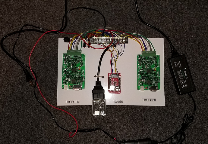
Thought I would share what my current development lab looks like. I also have the parts from a ~2002 truck on a different board but it is not working. This has been tested to be working. What you see are 2 ET7190-KIT boards from autoelectric.cn being used as simulators. I can automate testing with these modules easily. They support all of the same protocols that the M2 does although I am not sure how to get some of the items working on it.

These are tied to the top half of a terminal strip. As it is they can talk to each other great.

On the bottom of the terminal strip I have a M2 UTH hard wired to them. All of the wires from the M2 UTH are used except for the secondary CANBUS connections. There is also a ODB II cable wired in parallel with the M2 UTH to provide a connection to my M2 UTD or to a standard diagnostic tool such as my STN based ODBII to USB cable.

There is a power LED and a switched on LED. The power LED lets me see if power is getting to the board and the switched LED lets me know if the switch is on or not. Both LED’s would be lit if the 12 volt supply is feeding the network.

There is an on off switch mounted just left of the LED’s and there is a 120 ohm resister across the CANBUS lines to allow the simulators to communicate with normal diagnostic tools.

This setup will let me not only develop for the J1850VPW but other stuff as well. So I am happy I finally got this working the way it is supposed to. I wired a standard automotive power plug onto the end of this cord and have it connected to a 72 watt 12 volt DC power supply to supply power. This setup is pretty mobile too so I can bring it somewhere if I need to.

Each item can also be disconnected if necessary since the wires are wired to a plug and not hard wired to the board.

1 Like

This looks GREAT! Well done @redheadedrod. Having a clean, well built test fixture like this makes development and troubleshooting a LOT easier.

Quick head’s up: I think you have the ESP32 board plugged in backwards?

I put it on there for the purpose of the picture but I probably should mark the boards so I know which side is correct. I think it has been mentioned before that it is hard to know the proper way to plug it in. Would be nice if an outline of the “chip” would have been stenciled on the board to insure it is obvious.

I JUST got it fully mounted last night so I haven’t used it much yet but it did test out great. So we shall see…

Rodney

@redheadedrod - I bought one of these boards, and got it in today. Was trying to set it up to simulate some CANBUS. It appears to have come with the jumpers where they need to be for CAN. Everything on JP11 but the NC.

Their user guide at times is tough to piece together what they are trying to explain.

Right now, all I want to do is simulate a signal to a hand held scanner.

So you said you needed to apply power to the + and - ports. This is on JP6, and are you applying the full 5Vs? I did see mention of the 120 OHM resistor, but only saw it mentioned when hooking up two of these boards together.

Sorry to dig up this thread, but this is seriously the only place I have found anyone using this thing :crazy_face:. I’m hoping you can get me going in the right direction.
Thanks!

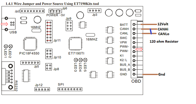
If you are talking about the ET7190kit module. To do CANBUS you MUST have the ground connected, the +12 volts connected and the CANBUS hi and CANBUS low.

The ground MUST be the same ground as on your other devices.

I found I HAD to have a 120 ohm resistor between the two CANBUS lines. Then it works fine with the M2 or other scanners. I actually have two of them talking to each other as a slave and master to create traffic so my M2 can read and respond. Their instructions say the 120 OHM resistor is not needed when two of them are communicating but that was not what I found to be the case.

@redheadedrod - Correct, I was referring to the ET7190. Sorry, should have been more clear.

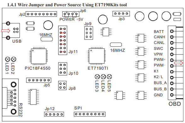
So this is how I currently have the board configured based on reading the docs.
Board%20Diagram

I am powering it now off USB.

From your comments, I need to build a cable where I can send +12V to the BATT on the OBD connector, along with ground.

How do you have this cabled? Some sort of T so power can go to this board and the real OBD connector that is on the actual handheld scanner? The scanner I have is powered via the OBD connector.

And if using just one of these ET7190, there is no 120 OHM resistor needed, right?

I brought your posts over to this topic which is a better fit. Check out the picture a few frames up.

And here is a picture of what is required for the CANBUS. The rest of the ports should be directly connected to the ODBII port.

As I already said, The documentation says you don’t need the resistor only when connecting two of these units together. I found this to be wrong and have to use a 120 ohm resistor regardless of configuration.

In the terminal strip I have pictured above the two units go into the top side of the strip. The port and the UTH are wired to the bottom of the strip. If you look at the picture you can see my resistor mounted on the bottom side of the terminal strip just left of the red power cable. It is very small. No reason why you couldn’t do the same at the strip or elsewhere. Just need it between those two lines somewhere.

@redheadedrod Appreciate this! I’m glad you moved the posts here. Didn’t want to dirty that other thread.

I need to get a 120 OHM resistor. I already have a power supply, and the way you built that board does make things simple.

Also just purchased an M2 UTH. I have been using an Arduino 101 (Intel Curie based), and a Sparkfun ELM327 kit. Never heard of the M2 until searching for a CAN emulator. Wish I would have found this earlier.

I found this emulator before finding the ET7190: https://github.com/carloop/simulator
But my soldering skills are not anything close to be able to do those ultra small components on that board. They don’t sell a put together board, only DIY.

No problem. The power supply was bought off amazon and has a lighter socket which is not viewable on the picture. At the top left I have a switch to turn the power on and off and a couple LED’s. One shows power to the switch and one shows power to the board. The two simulation boards and the terminal strip are taped to the board using 2 sided tape and the ODBII plug has a wire strap holding it down.

I also got my other test lab running.

My Issue was that I had a IP (Cluster) and BCM connected. They apparently need a wake up command otherwise they don’t talk. I just added the PCM to the board last night and now they are all talking.

I am currently working with a group that is making an open source flashing system for Pre Canbus GM’s (J1850VPW). My main gift will be getting the M2 stock hardware to work with it. I have some amazing things planned for it. Eventually it will be possible to fully tune supported vehicles remotely.

Rodney,

Been fighting with this board, wanted your input on what I might be doing wrong.

I want to use the ET7190 as an OBD Sim on the CANBUS.

Whenever I go to click on Start, I get the message below:
“Please Plug into USB wire (ET7190 Eval Board Jump to SPI Mode) click in Main Operate Menu!”

From your screenshot above, I know you were just placing them there, but is that how everything should be when you apply power to all the devices? Or do you need to keep the laptop connected via USB?

What is your setup for JP6, JP9, JP11, JP12, and SPI?

Thanks!
-Trey

I did not mess with any jumpers… Leave them as they came.

You must provide +12 and ground to the boards or they will not work.
You must have a 120 ohm resistor between the CANBUS lines or it will not work.

The ET7190 board is just an interface, it does not have any program logic on it to be able to run on its own so you MUST have it connected to a computer running their software (or your own) through the USB port. There may be other methods to connect to the board but I only use the USB connection and use their default setup.

Note that my boards are currently only used for my Development of M2 software. Which I should be getting back to within the next week.

Rodney,

Got it!

So it was two issues. I somehow stumbled into device manager for something else, and saw that “Unknown Device”. It was for the board. Dumb mistake on my part, though for some reason never saw it in the docs. But I should have known.

Now the software properly sees the ET7190, but it wouldn’t communicate with the hand-held scanner. So I got in some new WAGO connectors the other day, and tried them out instead of using the terminal block. The WAGO connectors only need you to strip the wire, and then it plugs in and locks down. Sweet little connector. After this, everything was golden.

Have you done much with the software on customizing what the simulator is sending to the scantool?

Thanks for all the help!

-Trey

It is a command response type system. I have not played with it as it does what I need as is. When I get into more specific items I may decide to go a little further with it.