Bounty - Help find a bug, we'll send you a book

Help find a bug!

Issue:

Cannot toggle pin PB27 when “Macchina M2” board is selected.

Background:

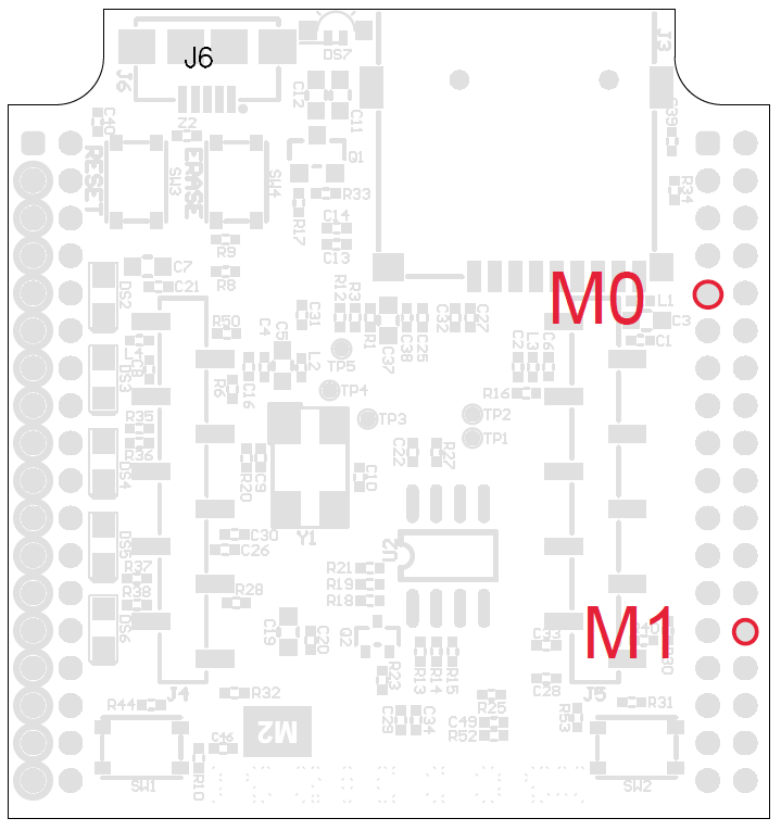
The Single-Wire CAN transceiver (TH8056) found on the M2 interface board has 2 mode pins (M0 and M1) that select between Sleep, High-Speed, High-Voltage Wake-Up and Normal Mode. Here is the SWCAN library.

We’ve got M0 connected to pin PB27 on the SAM3x8E processor (signal is named SWC_M0 on schematic). For some reason, this pin will not toggle when “Macchina M2” board is selected. A quick test sketch toggling the mapped pin name SWC_M0, doesn’t work:

void setup() {
  pinMode(SWC_M0, OUTPUT);
}

void loop() {
  digitalWrite(SWC_M0, HIGH);   // turn the LED on (HIGH is the voltage level)
  delay(1000);                       // wait for a second
  digitalWrite(SWC_M0, LOW);    // turn the LED off by making the voltage LOW
  delay(1000);                       // wait for a second
}

BUT toggling pin 13 (also PB27) with “Arduino DUE (Native USB Port)” board selected like this work!

void setup() {
  pinMode(13, OUTPUT);
}

void loop() {
  digitalWrite(13, HIGH);   // turn the LED on (HIGH is the voltage level)
  delay(1000);                       // wait for a second
  digitalWrite(13, LOW);    // turn the LED off by making the voltage LOW
  delay(1000);                       // wait for a second
}

So there is a bug somewhere here maybe? It sure does look similar to the Arduino Due board files here.

For easy probing, here is a diagram showing where to find M0 and M1 on the processor board. You should see 0 or 3.3V levels.

Bounty:

Besides the satisfaction of knowing you are helping to move the car-hacking community forward, we’ll send you a copy of The Car Hacker’s handbook.

Do a pull request in Github or reply to this post with what you figure out!

_MG_0711

Thanks!
Team Macchina

This is assuming the TH8056 isn’t pulling the pin down in any fashion, correct?

Edit: nevermind. Hooking it up to a meter shows that under Macchina M2 (Beta) for me it doesn’t affect the port at all. It is in the software level it seems.

A good question though! I believe the datasheet says that the TH8056 has weak 100K pullups on both of the mode pins.

Was delayed a bit sending my transmission off to be dissected. From my testing I can’t get PB27 to pull up at all, even with just the processor board. I tested the voltage at the microprocessor itself and PB27 never comes up when either M2 board configuration is selected. Checking the options in the pin definitions don’t show anything odd… I’ll keep looking into it, but it’s definitely in the M2 definitions.

Are there major differences between the M2 Beta (which I have) and the final production boards?

In this case there is no difference between the beta and production version. Either one will have this same issue. Full disclosure, I actually found the bug and will be fixing it in the board definition soon. But, I don’t count in terms of this contest as I essentially work at Macchina. :wink: So, if you can find the bug before I patch it then you’ll probably still win the prize.

A little hint for everyone: it is in the variant files. You should find something in there that makes a difference between the M2 variant files and the Due variant files.

Another hint: Ye, if you used a real Arduino Due and compiled a sketch with the M2 board files then the Due would also have this same issue. This is entirely an issue in the CPU and the software, not the boards themselves.

Well, I wish I’d read your hint a lot sooner, as it would have saved me many hours of wracking my brain trying to debug issues in the pin definitions that likely didn’t exist!

Apparently it’s the call on line 500 of variant.cpp enabling the channel for the temperature sensor that causes it to stay pulled down. I’m guessing it’s in the processor and it’s the two pins being tied together somehow? Commenting out that particular line fixed it for me, but I’d like to know what the root cause was.

Is it a plausible assumption that the built-in LED being tied to PB27 and the relation to the temperature sensor have something in common on the DUE boards?

You’ve got it. If the CPU temperature sensor ADC is enabled (which is on line 500) then pin PB27 will never go high. I am not sure why this is. The documentation says that ADC15 is not tied to any pins. If you used the M2 board files but ran it on an Arduino Due the same thing would happen because the issue is completely within the processor. In that case you just would never be able to toggle the LED on the board.

And, yeah, I spent a lot of time looking at the pin definitions too. I could never find any difference. It was only when I finally looked at the setup code for the Due as compared to the M2 that I saw that the M2 does a lot more ADC set up than the Due does. So, I commented out all the new code and re-enabled lines one by one. It worked up until the call to enable ADC15 was issued. Then it broke. Commenting and uncommenting that line would switch back and forth between working and not.

So, good job, you successfully found the issue too! Later this week I will remove the CPU temperature ADC setup and from then on single wire CAN will actually work properly.

Great Job @DivinityArcane!

Send me your address via DM and we’ll ship you a Car Hacker Handbook.

You mentioned you are using an older Beta M2? Do you want a new M2? We’re catching up on backorders now, but can ship you a new one later. Just let me know. Thanks for your help here!

Thanks @josh!

I actually am just getting back into programming and all that so this was a bit fun for me as well, but I’m still down for a copy of that book. I’ll get my address sent.

I’d love a new revision of the board, I’ve been putting it to work since I’m getting my truck going and any improvement is very much welcome. Let me know once the backorders are all taken care of!

It bugged me a little bit that there was this interaction within the microprocessor, so I looked into it this morning and read a bit into the datasheet for the SAM3X8E. After doing a bit of research, it’s apparently not completely unintended. According to Atmel case #00042100, enabling AD15 loses all GPIO capabilities for pin PB27. It’s a double-edged sword that if you want to use the temperature sensor, you lose an output pin due to it occupying the internal bus that PB27 would use. It’s weird, but it looks like there’s no workaround. I suppose you could enable AD15, get your reading, then disable it every single time you read the value of the temperature sensor, but in a non-blocking context that would probably still be detrimental.

In any case, at least it doesn’t bug me anymore. :rofl:

Wow, great job finding that! I looked up that case and found the Arduino Due forum thread about it. Apparently it really is undocumented but Atmel knows it exists. What a rotten thing to do! “Yeah, we’ll just silently disable one of the GPIO pins and NOT TELL A SOUL ABOUT IT!” Wankers…

1 Like