Bluetooth module setup

Trying to get the Blue Tooth module working and running into a problem…It powers up and LED blinks 2x per/second…I can’t talk to it via serial monitor. No response to AT command. The problem appears to be that the TX/RX pins on the socket and the module are not the same…The module schematic wants TX/RX just below the power pin 1, on the M2 schematic the TX/RX pins appear to be on the other/opposite side from the power pin. What do I need to do to make these compatible?
module schem
http://www.14core.com/wiring-programming-bluetooth-bee-xbee-communication-module/

I misunderstood the M2 schem, seeing the actual socket schem on page 6…The actual prob is the RX/TX pins are reversed between the 2…

Pretty sure that diagram is showing the pinout from the bottom view of the module. Did the headers come pre-soldered?

For reference, here is the schematic for M2:

https://github.com/macchina/m2-hardware/blob/master/M2/Processor%20Board%20Schematic.pdf

Page 6 shows XBEE socket schematic. Top Left is +3.3V. This pin is closest to the USB connector on M2.

Seeing the actual XBee socket shem on page 6, The TX and RX pins are reversed between the two. How do I fix this?

OK, this is a different question than you had before. Your module says “TX/D-OUT” for pin #2. This is data coming OUT of your Bluetooth module and INTO the RX pin of M2, also known as “XB_UART RX”. Same goes for the other pin.

In other words, there is nothing to fix electronically as long as your module follows the XBEE “standard”.

Can you post the code you are using to talk to the module? Maybe that is the issue?

The instructions I’ve found for using the module say to upload a blank sketch, so I’m not using any code…

I just split this topic away from the ELM327 discussion since this is sort of a separate thing.

You are going to need some code on M2 for your project to work. Your instructions are probably assuming you are using a Arduino UNO as a Serial adapter. We’ll post up some code in the docs here soon.

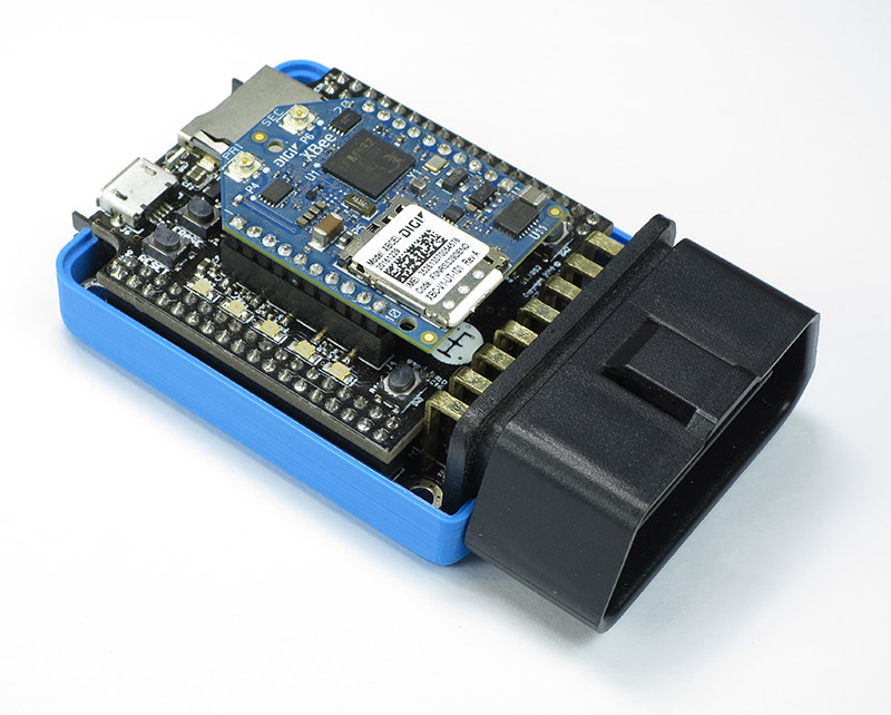
Slightly off topic. Working on connecting XBee format BLE module to M2 as well. Guess we could reasone socket connection direction from pictures like below.

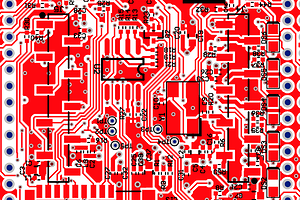
But when I look at PCB layout files,

Both in line connectors have dot with them. We can always ensure connection direction by measuring electrical connections. But it might be less confusing only leaving PIN1 indication on the right connector.

Hey @ianboyanzhang, Good point here. Those pin-1 location dots in the silkscreen are probably specific to the individual 10-pin connectors and not the whole Xbee socket.

We just added a diagram to the docs that should clarify xbee module orientation here:

http://docs.macchina.cc/m2/technical-references/communication.html#xbee-compatible-socket

1 Like