Adding a third CAN BUS?

Is it possible to add a third CAN to the M2? I have a specific application that I need to use the man in the middle configuration but then stop certain messages and route them to a different CAN.

I’m just not sure if there is a way to add an external CAN with another library. Anyone have any incite or advice?

I have made a dual and triple CAN Device using the atmega32u4 but it just doesn’t seem to be fast enough to handle the man in the middle and re route messages at the same time…

I will be building a method this summer but won’t be available “right away” that should allow you to do this.

I will be building a bridge that will allow two M2s to connect in a master/slave configuration which will allow you to double the ports. Note that this is only part of my over all project so it will be addressed later in the summer. The intent is that the final product will provide double the ports but you will be able to access as if the M2 suddenly had double the ports. Likely will be setting it up to be able to work through the external UART, the external SPI or the XBEE port.

Technically it does have a third CAN bus - single wire CAN. That might work OK for reading from a CAN bus at any rate. Otherwise, an SPI interface is available on the 26 pin connector. You could breadboard a MCP2515 module along with a MCP2551 (or some other transceiver). Then you’ll have a fourth CAN bus and you can use it for anything you want.

I know I can hook it up that way but my concern is using another CAN library. For instance the library I use now also initialises using CAN0, CAN1… It also uses the same file names “mcp_can.h”.

So would a new library need to be made altering all the names so there is no confusion? That’s the part I’m unsure of not building the external device.

On another note, Microchip is not recommending the MCP2551 anymore. They are pushing for the MCP2561 that supports the needed speed for the new FD CAN. I haven’t used the new chip yet but thought it worth mentioning.

Hey, that’s supposed to be super secret! :wink: Yes, the MCP2562FD replaces the MCP2551 and supports FD rates. As long as you’re at it at that point you might as well use the MCP2517FD module too. Of course, it’s brand new and finding a library that supports it would be kind of tough at this point. There are some out there, including one buried in a github repo of mine. But, nothing for the M2 at this point.

Still begs the question, how do I make an external CAN work with a new library without conflicting with the current?

Just don’t name the objects the same as the built-in ones. So, maybe call your new CAN object CAN2 or CAN3 or whatever you want. Use a different chip select pin too. Then nothing should conflict.

You can even use the same library as the built-in stuff. For instance, if you were using the mcp2515 library you could create another object for use with your externally connected chip:

MCP2515 CAN3(yourCS, yourIntPin);

Then create an interrupt callback routine for it:

void CAN3Handler() {
    CAN3.intHandler();
}

void setup()
{
    attachInterrupt(yourIntPin, CAN3Handler, FALLING); //enable interrupt
}

Then you can initialize it:

CAN3.begin(500000);

And you’re off to the races.

You’re allowed to create as many instances of the MCP2515 class as you want. You just need to use a different chip select pin each time, a different interrupt pin each time, and set up the interrupt callback for each one.

Great info…

I did pull another library and for lack of creativity renamed MCP to ANY. Then figured out that CAN can’t be used because it defaults to CAN0. Without hooking up hardware it all compiles with the dual built in CANs enabled.

Then the problems start.

The Pin Documentation is so brutal I can’t figure out what to use for a CS. The information is wrong in the documentation, I found that CS2, although in the documentation says its there… ITS NOT!.

Using SPI_CS2 which is what the documentation says to use just throws an error. I thought about using all the PINS from the XBEE so I could make a board to mount to the Macchina but all that documentation seems to be wrong as well. Or at least not trustworthy. The pins listed in the documentation don’t match the schematics properly. And the documentation under the XBEE pin-out are missing all the pins for the SPI.

I honestly don’t know how anyone new develops with this board… Hours of wasted time.

Sorry… Really stressed over how much time I wasted trying to get this working yet 5 minutes with a Due and I have an external CAN up and going.

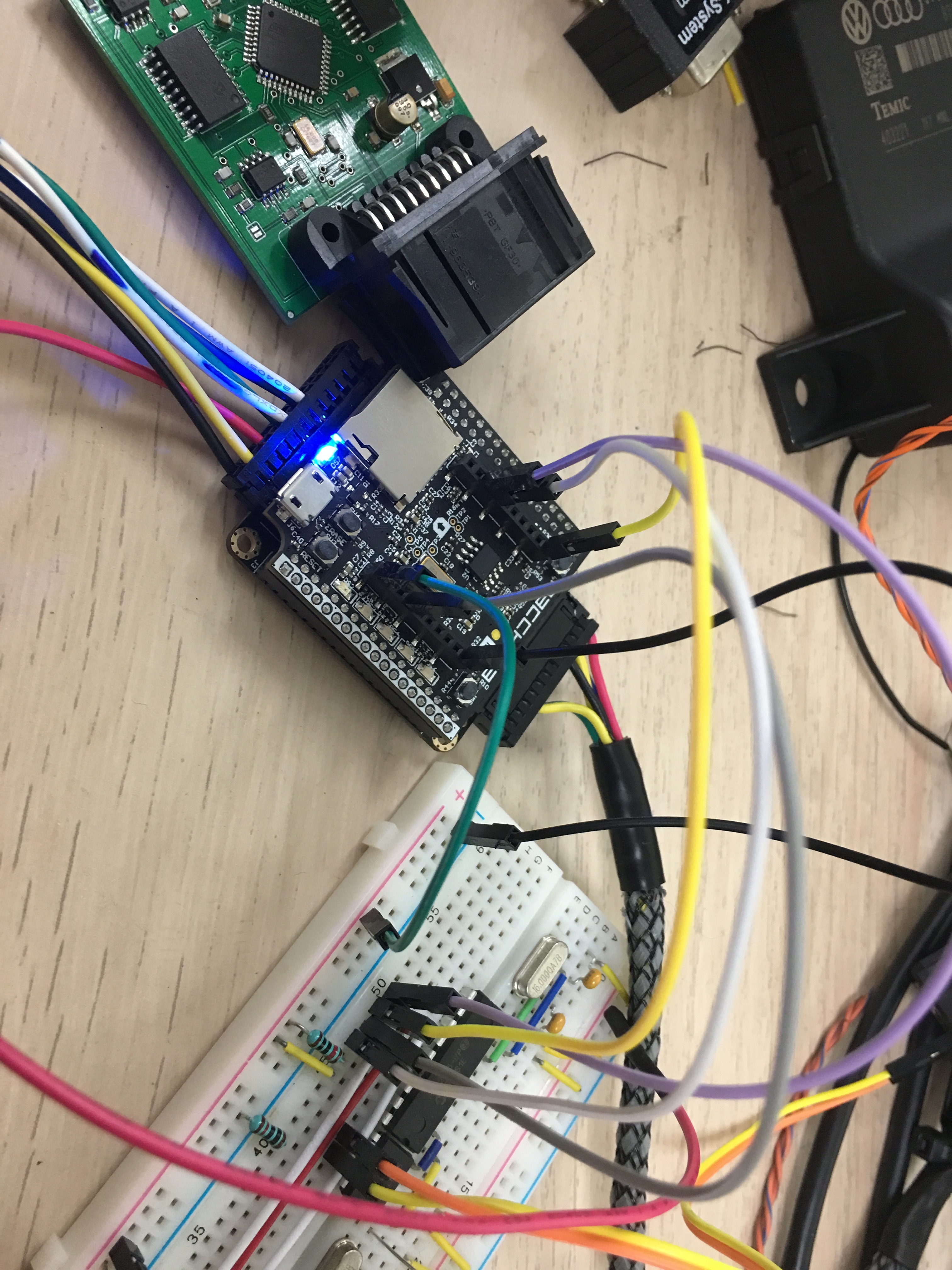
This is what I have right now…

26 Pin Connector.

Pin 11 - SCK
Pin 12 - MISO
Pin 16 - MOSI
Pin 20 - +5V
Pin 23 - +3.3v (broke it out just in case the 2515 had to match MCU voltage… It doesn’t…)
Pin 26 - GND

I did try PIN 15 for CS which is shown in the documentation as USART2RX and SPI_CS2 but I have no idea how it’s called in the sketch since the listed names and other variations of don’t work.

Ultimately the XBEE would be a cool way to do it but getting a CS and proper pin names and locations are first.

So any idea where I can find a CS pin to use or what to call it in my sketch?

Success… Using Altered Seed Studio library and using compiled Pin Number instead of name for CS2… Now to see if I can merge my two CAN codings to do what I want :slight_smile:

I’m using CAN3 as it seemed CAN2 was a keyword I figured it belonged to the M2.

XBee only has UART support if I recall. It was mentioned to possibly add SPI to it but not currently there.

According to the schematics it’s there.

Just be careful with powering the MCP2515 with 5v when the M2 is 3.3v. SPI will have the sending end use its own voltage level for the SPI signal. So, in your case I’d imagine MOSI is running 3.3v / GND and MISO is running 5V / Gnd. This means the M2 is getting 5V on a 3.3v pin. That could work for a while but it also could burn out the MISO pin. Unless the SPI pins are 5V tolerant but I don’t think they are.

Ill have to look again then. I thought it was mentioned that it didn’t have one. Would be another option then to have a very fast connection to use the Xbee port.

I just checked with multi-meter and it’s there. If I have a chance later today I will switch over to it with my CAN BUS and confirm it’s all working with the CS pin that’s there as well.

Here you go… CAN BUS running off of the XBEE ports. I had to use the 5v from the harness for now because I only have 2551 chips. But by using a 3.3v if there is such a creature a shield could be made to add a third CAN BUS or any other 3.3v Device that needs SPI. Off to eagle to see what I can whip up…

Well if you run across a way to provide full speed USB access via XBEE SPI I would be interested in seeing that too. The current USB port is limited by serial speed but I was hoping to look into the SPI external port to provide a much faster connection but XBEE could be another option as well.

Thats out of my relm. But a quick search turned up this.

https://www.mouser.sg/new/microchip/microchipmcp2210/