2017 GM HMI Calibration / VIN setting

I’m new to this forum, so excuse my ignorance if this topic is covered elsewhere. I have 2 2017 Camaro’s (1 ZL1 and 1 RS 1LT). I’ve recently updated the HMI module in the RS from the IO5 (non-nav) to the IO6 (NAV). However, programming it via the SPS system allowed it to work, but I had to use my ZL1 VIN to get the calibration files needed to activate the navigation and other features. With all that said, there is an invalid VIN on the HMI and it stops me from accessing the SHOP and other OTA updates. I would like to simply update the VIN to the appropriate VIN for the car without affecting the calibration files.

I’ve been reading about CAN BUS programming and sniffing, but have not found a solid article on the ECU VIN updating. Security for the HMI is low compared to the instrument cluster. (That was updated recently, but programmed by a professional.) Does anyone have anything that can point me in the right direction?

Hardware currently owned… and working on…

MakerFocus CAN-BUS Shield V1.2
kuman Arduino UNO R3 Mega 2560 board
DB9 Serial RS232 Female Port to Male OBD2 OBDII

I have an M2 (under the dash) on order… if that is more useful than the Arduino board

Sorry for the extra replies… I do have access to SPS for both vehicles and use a VXDiag or GM standard OBD2 MDI programmer to program via the OBD2 port.

I’m no expert in this. The only thing I can think of that I could do would be to use something with two CAN buses as a man-in-the-middle board. Frames come in one bus and go out the other. There will likely be a certain ID that transmits the VIN number over the bus. If you can intercept that ID then you can send out your own custom frames that transmit the VIN number you really want it to. That’s really a kludge but absent someone who knows how to reprogram the ECU itself it might be the only viable option. You can find that ID (if it exists) by capturing traffic and looking at that traffic as ASCII to see if you can find the VIN number getting sent over the wire.

I know someone who does it, but it’s a business. Trade secrets are not just handed out. Since I know it can be done, I was hoping someone in the community would have some knowledge. Your theory sounds pretty logical though

So I wrote out a long reply and it created a server error… Go figure…

Basically for the older J1850VPW (Pre CANBUS) there is a method of changing memory locations. This should be similar for CANBUS stuff. The biggest issue will be knowing what address to change in your Navigation unit. Which you can find out if you can get the firmware from the unit. if it isn’t specifically written in the Firmware the firmware should point you in the right direction.

Note that this could very well take you hundreds of hours to reverse engineer. I only know this information because I am watching some guys who are close to having an open source solution to programming older PCM’s and similar methods will likely be applicable to newer PCM’s as well so hopefully a CANBUS version won’t be far behind.

This same method should be similar for any modules in the car that are programmable via SPS.

Unless you or I get someone that has already done the work to do this it is likely not going to happen. If someone reading this wants to forward me information on how to do this quietly I can certainly make it happen.

Your best option is to have the guy you know do it for you. Should only take a very short period of time.

Or talk to the guys at:
https://www.gm-navigation.com/

I have a similar issue with a “Silverbox” Navigation unit I want to install in my 2009 CTS. And haven’t given up on figuring it out yet but don’t have the time right now. So may just pay the guys mentioned above to give me an already VIN matched radio.

Thanks. It would be nice to know how to do. But the guy I use not only can program this module, but also the instrument panel cluster. I think he works with gen5diy and does work for them. Chris at White Auto and Media Services. I don’t think he’s going to let the knowledge on how to get out though.

If Chris is the same guy I know about that is in Detroit and does this sort of thing for a bunch of different things, yea no way he will be sharing that information. Even though he got it from other people himself. I believe if it is the same guy he may actually work with the guys mentioned at the link I gave to reprogram the radio VINS.

Yup… he’s the man.

Yea on the forums I am on he figured out how to “crack” the GM Navigation unit I have sitting here and didn’t say how he did it but his threads just stop. So I went as far as his threads suggest and I have been off on other things since. Trying to connect to him on Facebook and other places just have come up empty.

So goes back to the “Better off paying them” unless you have the skill and abilty of doing it yourself.

I quite literally reverse engineer GM modules on a daily basis as my full time job. Same as what Chris does, except I’m down in Aus.

Anyways, onto your problem!
Generally speaking, there is a three step process before being able to changing anything such as a VIN in GM modules.

  1. Read the current setting/VIN/Option (ALWAYS do this)
  2. Perform security negotiation (allows access to make changes… this is sometimes needed to even read)
  3. Write change to module

Step1 is the part the scantool performs when displaying on screen. Step2 is the difficult part which requires reverse engineering algorithms, this is the part most get stumped on and cannot get past!

Step3 is basically just an extension of step1, just using a different mode.

I know its not an exact answer… but least you have a basic idea of whats to be expected.

1 Like

Thanks Tazzi! I am awaiting my M2 to come in the mail. Currently I only have the Arduino board and the CAN Bus shield. Once I get the M2, I’ll try to play with this. However, I’m assuming that this type of work should be done to the module outside of the vehicle on the bench. Basic power supplied to the module and tapping into the CAN bus connections on the module. The reason I ask, I have the GDS2 software and could essentially sniff the traffic. I know that I can read the VIN of the car, but have not looked at the actual module reading other than pulling calibration information from the module using it. I suppose those packets would be useful as part of that group is the VIN.

Always bench.

I chose bench since i have a dedicated power supply… so no flat batteries. And less CANbus traffic from other modules in the way. Although the extra traffic doesnt really matter when you set the correct filters to only see information related to the module in question.

In GDS2, when you go into the module and it brings up module details including calibration numbers, part number and VIN, these are all direct requests to the module which are good to sniff at the beginning. As you need to know which DID (think of this as a specific data identifier) to request before you can even think about trying actually change the VIN.

One other thing while Im thinking of it. Is you will need to check if the module is on HSCAN (Normal dual wire CAN) or gmlan (Single wire can). Otherwise your arduino+CAN shield wont be of much help! But the M2 has a dedicated CAN controller for gmlan, so youll be covered for both scenarios when that rolls up.

I recommend starting to get wired up on the bench now, and work out if its HSCAN or GMLAN, so your prepped and ready to go.

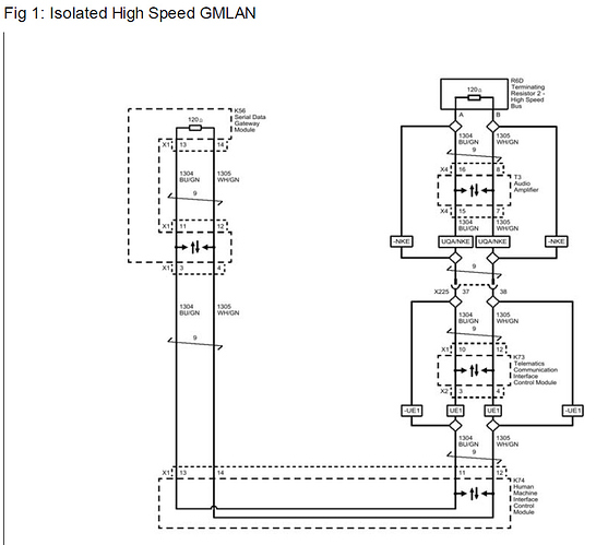
Looking at the wiring diagram, there is the LIN bus and HS GMLAN 2 wire +/- circuit on X1 of the HMI module. Depending on the option codes IO5/IO6-UQT … determines if it’s wired to pins 11/12 or 13/14.

Cool.
The terminology can be a little confusing. When is says HS GMlan 2 wire (+ and - wires), this this is your ordinary dual wire HS CAN.

To keep things simple, I only use the word GMLAN (also known SWCAN) for the single wire CAN interface.

Don’t worry about the LIN bus. The CAN line is what we will want. Since LIN is not even accessible from the OBD port.
Are you sure they dont both use 11/12 and 13/14?. Could be an optional secondary bus used for specific addons?

You probably know this… but my brain needs to spit it out… I will have to physically look at the wiring harness in the car, but historically if the manual has the option codes listed (IO5/IO6 - UQT)… it usually means those wires are not there if you do not have that specific option code. In the case of the instrument cluster, I noted 2 sets of MOST bus wires. But when reviewing the wiring diagram, it was almost like it was a “throughway”. One side went to the HMI and the other side went to the Amplifier to complete the circuit. I’m not sure if this is a similar scenario.

As I suspected. It looks to be some sort of throughway…

Once I get connected and see traffic, what is the best way to change calibration files loaded onto the module? Is there a “file directory” available? Just send BIN files? I know my explanation is basic, but want to figure this out. There is 1 specific calibration file that I need changed out that I have in my SPS cache from the SPS site, but because it was part of my other VIN, i obviously cannot just throw it at the module with SPS and lose my other features.

Ok, so looking at that diagram, I now understand what you were referring to.

So pin 13/14 is what we want (I think??)
The reason there is two sets of CANbus wires, is because I believe manufactures are trying to isolate some of the vehicle to prevent any direct hacking through items such as bluetooth or other wireless devices. I think some proof of concept videos emerged showing some cars being hacked through their wireless connectivity which allowed the user to completely control the car.
Not sure if this situation is the case… but I do recall reading up on it.

Anyways, back to it.
Unfortunately its not that simple. You can’t “pick and chose” files using sps, and theres no software out there which simply takes a bin and throws it into your module. This is where all the fun begins (Or… pain depending how you look at it?).

Re-flashing entire calibrations is not for the faint hearted. This is quite a leap from trying to change just change basic options such as the VIN. Its a quick way to bricking and killing modules through custom flashing if done incorrectly, probably dont recommend looking at that for what your trying to do, seems your main task is the VIN.

Also, MOST is usually very highspeed CAN. Its a bit special the way it works… I personally havent really messed with MOST much before, but its usually used between something like a radio screen and radio main processor to send information, video and audio.

MOST is not what we want to connect to… we want the actual diagnostic communication CAN lines which are the ones used for flashing.