12 VIO Sink and Source Questions

Hi,

I have some questions on the 12V outputs on the M2. I am starting a project (chevy bolt HV battery control/monitoring/charging) which needs to drive 3 contactors and 3 signals of 12V+. The connections to the contactors and devices contain a common ground pin and 12v+ pin for each the contactors and enable devices inputs.

I am not sure exactly what the sink outputs of the M2 are and how/if they can be used for my purpose. (sink and output seem somewhat opposite to me). A quick explanation of how to use the sink outputs would be appreciated.

12Vio Library questions
The M2 guides states 12Vio pins 2,6,10 are source outputs, while pins 14,18,22 are sink outputs. The 12Vio library function Setpin_12VIO takes parameters including Source_Mode.and Output_Pin.

  1. Can the Source_mode actually be set or is it “wired” on the pins stated above?
  2. What is the mapping of the enum Output_Pin to physical pins (i.e lowest to highest for both)?
  3. Can the M2 support 6 source outputs?

Thanks in advance for any help you can provide.
Brian

I want to note that the way this is documented is confusing. The 12V input and ground for the 12Vio are completely separate from the OBD2 side. So if you are using OBD2 and 12Vio, you need to run 12V and ground to BOTH sides of the M2.

The pin mapping in the library is also confusing. If you are using source or sink the mapping is like this:
Software | Physical
1 2
2 6
3 10
4 14
5 18
6 22

If you are reading the inputs, the mapping is this:
Software | Physical
1 1
2 5
3 9
4 13
5 17
6 21

Source means it supplies 12V. Sink means it provides a ground.

I believe the source and sink are built into the pins and can’t be changed. The way the library is written implies otherwise.

You can use relays to convert the sink ports into 12V sources. You wire 12V into 3 relays on pins 86 and 30. Attach a separate M2 sink pin to each relay pin 85 and the 12V outputs you want to pin 87.

Good feedback, hopefully this will also help:

Here is a decent tutorial describing the difference between high and low side drivers:

https://learn.sparkfun.com/tutorials/transistors/applications-i-switches

In general: If you want M2 to Ground a pin, use a SINK pin. If you want M2 to POWER (source 12V) a pin, connect to SOURCE.

In some early prototypes, we had the ability to set the output type with code (either source OR sync), but to simplify and save cost/board space, we decided to go with 3 SINK, and 3 SOURCE. In other words, that function will not do much with the current version of M2. We kept that fucnction in case we decide to add this feature back later in hardware.

The pin mappings can be found here.

A full pinout of the 26-pin connector (J5) can be found here.

and this page shows more detail for 12V outputs:

No, but as @crashmaxx suggested, you could do this with 3 relays.

The 26 pin connector (J5) has 2 Ground pins available. (pins 25, 26), and a constant 12V output (Pin 24).

Note:

When using the SOURCE outputs (OUT 1, 2, 3), you’ll also need to make sure I_SENSE_EN is enabled to be able source 12V and to monitor current flow. The library should do all of this automatically though.

And for reference, here is a link to the schematic of the interface board.

Thanks for the input.
Can you clarify one item please. The use of the 12VIO ground and 12V pins is not clear as crashmaxx’s response implies they are source inputs required to drive the 12V IO and your response states the positive pin is used for a constant 12V output. Where should the input power be connected?

I am also wondering a related question weither the other voltages are related to this as well. Ie the 5 and 3.3 volt supply outputs. I was under the understanding the whole unit was powered from the ODBII connector or the USB.

Sorry for the confusion here guys. Hope this helps:

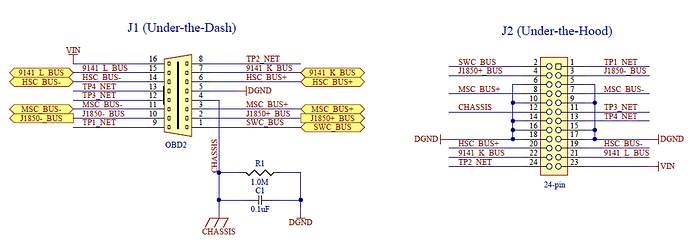
The ONLY 12 volt power input (VIN) on M2 is found on either J1 pin 16 (OBD2 connector in the case of UTD) or J2 pin 23 (24 pin connector in the case of UTH). Refer to page 2 of the Interface board schematic, with screenshot here:

Now look at page 5 of the schematic for pinout of J5 (26 pin connector). None of these are POWER inputs, ONLY power outputs:

+3.3V is a constant 3.3V OUT.
+5V is a constant 5V OUT.
+12VIO is a switched 12V OUT rail controlled by Q6. Perhaps we should rename this to make it more clear. The only thing between the +12VIO output and +12V is a fuse and Q6 switch.
+12V is a constant 12V rail. (Only think between +12V on this connector and VIN

In the case of when a USB connector is plugged in and NOT powered with 12V via J1 or J2, you will still see +5V and +3.3V on J5.

I hope that helps, if not, let us know!