Support for j1850 VPW/PWM?

Thank you very much Rodney! I tried running the sketch on my M2, and saw the following traffic:
23:26:14.946 -> RX: 48 6B 10 41
23:26:14.946 -> TX: 48 69 2D 4D 32 21 CC
23:26:17.197 -> RX: 48 6B 10 41
23:26:17.197 -> TX: 48 69 2D 4D 32 21 CC
23:26:19.377 -> RX: 48 6B 10 41
23:26:19.377 -> TX: 48 69 2D 4D 32 21 CC
23:27:12.748 -> RX: 48 6B 10 41
23:27:12.748 -> TX: 48 69 2D 4D 32 21 CC
23:27:14.386 -> RX: 48 6B 10 41
23:27:14.386 -> TX: 48 69 2D 4D 32 21 CC

This is me turning the key 4 times from off state to ignition state. I tried a couple of baud rates:
10.4k (10400), the default 115200, and in both cases the output was the same as above.

Iā€™ll try it out with an ELM tomorrow and post any updates here.
Question: How do I read the RX message? i.e. are all bytes data only?
Thanks
Karan

This just shows the bytes as they are received. You will have to convert them to their proper data. This sketch was only a simple one to show it working. As far as I know no one has tried to make it better yet.If they have, they havenā€™t shared it.

@redheadedrod - this is awesome!
I tried the ELM device with a Y connector as you mentioned. I get the following messages:
16:06:17.283 -> RX: 68 6A F1 01 01 0A
16:06:17.317 -> RX: 48 6B 10 41 01 00 07 E1 E1 A3
16:06:17.398 -> RX: 68 6A F1 01 01 0A
16:06:17.432 -> RX: 48 6B 10 41 01 00 07 E1 E1 A3
16:06:17.683 -> RX: 68 6A F1 01 01 0A
16:06:17.716 -> RX: 48 6B 10 41 01 00 07 E1 E1 A3
16:06:17.953 -> RX: 68 6A F1 03 CD
16:06:18.243 -> RX: 68 6A F1 03 CD
16:06:18.523 -> RX: 68 6A F1 03 CD
16:06:18.771 -> RX: 68 6A F1 07 B9
16:06:19.071 -> RX: 68 6A F1 07 B9
16:06:19.334 -> RX: 68 6A F1 07 B9
16:06:19.419 -> RX: 68 6A F1 02 00 00 29
16:06:19.472 -> RX: 48 6B 10 42 00 00 7E 1A 00 00 F4
16:06:19.566 -> RX: 68 6A F1 02 02 00 B1
16:06:19.566 -> RX: 48 6B 10 42 02 00 00 00 89
16:06:19.837 -> RX: 68 6A F1 01 01 0A
16:06:19.837 -> RX: 48 6B 10 41 01 00 07 E1 E1 A3
16:06:19.911 -> RX: 68 6A F1 09 00 4D
16:06:20.614 -> RX: 68 6A F1 09 00 4D
16:06:21.259 -> RX: 68 6A F1 09 00 4D
16:06:21.777 -> RX: 68 6A F1 09 00 4D
16:06:22.479 -> RX: 68 6A F1 09 00 4D
16:06:23.129 -> RX: 68 6A F1 09 00 4D
16:06:52.479 -> RX: 48 6B 10 41
16:06:55.228 -> RX: 68 6A F1 01 01 0A
16:06:55.323 -> RX: 68 6A F1 01 01 0A
16:06:55.420 -> RX: 68 6A F1 01 01 0A
16:06:55.550 -> RX: 68 6A F1 02 00 00 29
16:06:55.640 -> RX: 68 6A F1 02 00 00 29
16:06:55.736 -> RX: 68 6A F1 02 00 00 29
16:06:55.872 -> RX: 68 6A F1 02 02 00 B1
16:06:55.973 -> RX: 68 6A F1 02 02 00 B1
16:06:56.073 -> RX: 68 6A F1 02 02 00 B1
16:06:56.173 -> RX: 68 6A F1 01 01 0A
16:06:56.307 -> RX: 68 6A F1 01 01 0A
16:06:56.390 -> RX: 68 6A F1 01 01 0A
16:06:56.521 -> RX: 68 6A F1 01 01 0A
16:06:56.602 -> RX: 68 6A F1 01 01 0A
16:06:56.706 -> RX: 68 6A F1 01 01 0A
16:06:56.841 -> RX: 68 6A F1 03 CD
16:06:56.922 -> RX: 68 6A F1 03 CD
16:06:57.023 -> RX: 68 6A F1 03 CD
16:06:57.123 -> RX: 68 6A F1 07 B9
16:06:57.245 -> RX: 68 6A F1 07 B9
16:06:57.377 -> RX: 68 6A F1 07 B9

For brevity - I removed the line that sends ā€œHello M2!ā€ after each RX.
I suspect a majority of the messages are coming from the ELM device pinging various ECUā€™s on the bus. Of all the pings it seems the following messages get a response back - Iā€™m pasting the TX of ELM device, followed by response (RX):
16:06:17.283 -> RX: 68 6A F1 01 01 0A
16:06:17.317 -> RX: 48 6B 10 41 01 00 07 E1 E1 A3

16:06:19.566 -> RX: 68 6A F1 02 02 00 B1
16:06:19.566 -> RX: 48 6B 10 42 02 00 00 00 89

16:06:19.837 -> RX: 68 6A F1 01 01 0A
16:06:19.837 -> RX: 48 6B 10 41 01 00 07 E1 E1 A3

From this analysis - it seems Iā€™m only getting 2 messages from the car:

  1. 48 6B 10 41 01 00 07 E1 E1 A3
  2. 48 6B 10 42 02 00 00 00 89

Any tips/advice on how to read these?
It seems that even after doing multiple scans - these seem to be the only 2 messages returned. Am I missing something here possibly?

Happy to contribute to the code if I can get to the point where I can listen in on all the messages :slight_smile:

I set this project aside for awhile knowing it would be easier this winter when I didnā€™t need to keep the car in service. Well, itā€™s winter so Iā€™m ready to start back.

Before I paused, I learned/ deduced a couple important things that I thought Iā€™d throw out here in case they help someone else.

Each device on my class2 bus has two addresses: one it listens to and one it talks on. Thatā€™s HUGE. It may be common knowledge, but I never heard it and it really delayed me as I was filtering too much out.

Secondly, and this is important for my project where Iā€™m trying to replace the stock radio and retain features it controlled in other devices, is that all the devices need to send a heartbeat message frequently. If any device isnā€™t heard from for two seconds, other devices will stop responding to itā€™s commands and may even take over some functions themselves.

Does this trigger any thoughts / hints / ideas from you all?

Iā€™re reverse-engineered some of the protocol between the Head Unit and the 6-CD Changer in my '02 Yukon. Iā€™m using an arduino, but that wonā€™t matter for the protocol. Implementing the J1850 bus was not hard, but figuring out the messages has been a challenge. At least on my GM vehicle, the first 3 bytes are header, destination address, source address. For example, the heartbeat from the HU is:

0x08, 0xFF, 0x80, 0x03

So the destination is 0xFF (broadcast) and the source is 0x80 (HU). Source addresses are ā€œphysicalā€ addresses, and are pretty consistent. Destination addresses are ā€œfunctionalā€, and a device may respond to several. For example. 0x9B is the CD Changer system. Both CD and HU will send using that destination address. If any of this matches what you are seeing in your vehicle (did you say it was a Caddie?), let me know, and I can post more. CB.

Yes, thatā€™s completely in-line with what Iā€™m seeing. I was able to acquire all the control module ID numbers as well as the numbers emulated by the BCM and bridged to the high speed GMLAN, but what was really throwing me off was, like you said, some devices are responding to messages with multiple ā€œdestinations.ā€ Today was a big milestone. I was able to find and decode the outside temperature on the bus, filter for that, then display it on an OLED display. It comes from the HVAC (0x99) to 0xF3 with two data bytes and a checksum. Most of the project till be controlling the Bose amp and interfacing to the IR port of a Sony head unit. Yes, itā€™s a 2008 Caddy (XLR-V) and yes, Iā€™d love to hear about any other things youā€™ve seen and learned about the class 2 implementation.

Iā€™d be interested in learning more about the BCM interaction. I can set up the HU in my lab, but the CD changer wonā€™t fire up without the BCM, so most of my data capture has taken place out in the truck!

Hereā€™s a summary of what Iā€™ve discovered so far. My focus has been on the conversation between CD Changer and HU. Some is pretty obvious, but some is clearly conjectural:

Byte 0 = header.  Z-bits always 2 => multiple data bytes.  Address type always FA = Functional.

Source 0x80 = HU (Head Unit)
Source 0x81 = Amp?  Broadcasts hearbeat, and sends to 0x95
Source 0x82 = CD (Slave 6-cd changer )
Source 0x89 = Back Seat controller. Sends heartbeat, and a few messages at igntion on and off.
(Sources other than 0x8* filtered out)
OTher possibilities are Rear COntroller, and Overhead DVD

GM uses "functional addressing" for destinations
Dst 0xFF = Broadcast?  Always used for heartbeats
Dst 0x9B 1011 Functional Address "CD"?  Always used from both sources for everything but heartbeat
Dst 0x94 0100 FA maybe not CD?  Only sent by HU.  Seem to go with power on/off and insert disc
Dst 0x95 0101 ?? Sent by CD when ejecting disc.  Maybe saying "active/inactive"?  Only sent by 0x81 and 0x82
Dst 0xEA and 0xEB Only seen during ignition off, door open, etc.  Never from Cd (only 80 and 80)

Byte 1 = msg type

0x01 = Command.  Byte 3 is Command Type:
   0x01 - Next Track - reply with 0x0B 0x02 0x0F and 0x0C 0x00 0x0F
   0x02 - prev track - reply with 0x0B 0x02 0x0F and 0x0C 0x00 0x0F
   0x0B - CD Should start playing - reply with 0x0C 0x00 0x0F
   0x0C - CD should stop playing - reply with 0x0D 0x02 0x0F
0x02 = Reply to Command.  Usually seen only after 0x01.  One exception is when CD inserted.  CD sends unsolicited with 0x01 0x02 0x0F.
                                                     Also when CD ejected.  Send unsolicited 0x02 0x02 0x0F.
0x03 = heartbeat - sent to 0xFF by all components every 2 secs.
0x04 = track status
0x05 = Power down?  Sent when opening car door.
0x06 = mute. Sent by HU when switching away from CD.  CD Answers with same.
0x07 = sent by CD to 95 during eject sequence
0x30 = Sent by HU in shop at Power On. and off.
0x47 = HU -> 94 : Immediatley after 0x87 below.
0x93 = Always from HU to 94.  Can probably ignore.
0x85 = never sent by CD, Just HU when CD starts playing.  Never to 9B or FF, only 94 and 95. 81 always answers with same message.
0x86 = unmute. HU sends, CD Responds with 0x86 or 0x89
0x87 = CD -> 95 : Disc Loaded.  First command of that sequence.  HU responds with 47
0x89 = On Air.  HU Sends, CD Responds with 0x89
0x13 = never sent by CD.  Just 80 and 81 94 and 95 (never 9B).  Can probably ignore.

Byte 2 = (almost) always 0x80 or 0x81

Other messages from CD to HU
0x02 0x81 0x0B 0x02 0x0F  Perhaps "command received"?  Only after change track command
0x02 0x81 0x0C 0x00 0x0F  Perhaps "command complete"?  Seen when changing tracks, switching from FM to CD.
0x02 0x81 0x02 0x02 0x0F  When CD ejected
0x02 0x81 0x0F 0x02 0x0F  When CD removed (changer icon goes out)

From CD -> 0x95:
0x89 0x81  When switching to CD
0x86 0x81  When switching to CD (Resume)
0x07 0x81  Eject CD while playing
0x87 0x81  Insert CD

CD Broadcast heartbeat
H:0x08|P0|H3|FA|Z:0x0|dst:0xFF|src:0x82|Data: 0x03

HU Broadcast heartbeat
H:0x08|P0|H3|FA|Z:0x0|dst:0xFF|src:0x80|Data: 0x03

CD Insert Disc:
H:0xAA|P5|H3|FA|Z:0x2|dst:0x95|src:0x82|Data: 0x87 0x81                     CD: c87_im_ready
H:0xEB|P7|H3|FA|Z:0x3|dst:0x94|src:0x80|Data: 0x47 0x81                     HU: r47_you_ready
H:0x8A|P4|H3|FA|Z:0x2|dst:0x94|src:0x80|Data: 0x89 0x81                     HU: c89_on_air
H:0xAA|P5|H3|FA|Z:0x2|dst:0x95|src:0x82|Data: 0x89 0x81                     CD: r89_on_air
H:0xAA|P5|H3|FA|Z:0x2|dst:0x9B|src:0x80|Data: 0x01 0x81 0x0B                HU: c1b_start
H:0xAA|P5|H3|FA|Z:0x2|dst:0x9B|src:0x82|Data: 0x02 0x81 0x0C 0x00 0x0F      CD: r2c_start
H:0xCA|P6|H3|FA|Z:0x2|dst:0x9B|src:0x82|Data: 0x04 0x81 0x01 0x01 0x00 0x00 CD: track_status

CD Insert Disc (Radio off) (CD Light Comes on):
H:0xAA|P5|H3|FA|Z:0x2|dst:0x95|src:0x82|Data: 0x87 0x81                     CD: c87_im_ready
H:0xAA|P5|H3|FA|Z:0x2|dst:0x9B|src:0x82|Data: 0x02 0x81 0x01 0x02 0x0F      CD: c2_12f
H:0xEB|P7|H3|FA|Z:0x3|dst:0x94|src:0x80|Data: 0x47 0x81                     HU: r47_you_ready

Track Status (once a second):
H:0xCA|P6|H3|FA|Z:0x2|dst:0x9B|src:0x82|Data: 0x04 0x81 0x01 0x01 0x00 0x01
                                                    Disc Trak Min  Sec    All Values BCD

H:0xCA|P6|H3|FA|Z:0x2|dst:0x9B|src:0x82|Data: 0x04 0x81 0x02 0x01 0x00 0x59
H:0xCA|P6|H3|FA|Z:0x2|dst:0x9B|src:0x82|Data: 0x04 0x81 0x02 0x01 0x01 0x00
                                                    Disc Trak Min  Sec    Disc 2 track one rolling from min 0 to min 1

Skip forward one track:
H:0xAA|P5|H3|FA|Z:0x2|dst:0x9B|src:0x80|Data: 0x01 0x81 0x01                    -> Next Track
H:0xAA|P5|H3|FA|Z:0x2|dst:0x9B|src:0x82|Data: 0x02 0x81 0x0B 0x02 0x0F          <- Ack
H:0xAA|P5|H3|FA|Z:0x2|dst:0x9B|src:0x82|Data: 0x02 0x81 0x0C 0x00 0x0F          <- Part 2 ack next track ?
H:0xCA|P6|H3|FA|Z:0x2|dst:0x9B|src:0x82|Data: 0x04 0x81 0x01 0x02 0x00 0x00     <- track status
H:0xCA|P6|H3|FA|Z:0x2|dst:0x9B|src:0x82|Data: 0x04 0x81 0x01 0x02 0x00 0x01     <- track status

H:0xAA|P5|H3|FA|Z:0x2|dst:0x9B|src:0x80|Data: 0x01 0x81 0x01                    -> next track
H:0xAA|P5|H3|FA|Z:0x2|dst:0x9B|src:0x82|Data: 0x02 0x81 0x0B 0x02 0x0F          <- Ack
H:0xAA|P5|H3|FA|Z:0x2|dst:0x9B|src:0x82|Data: 0x02 0x81 0x0C 0x00 0x0F          <- ack 2?
H:0xCA|P6|H3|FA|Z:0x2|dst:0x9B|src:0x82|Data: 0x04 0x81 0x01 0x02 0x00 0x00     <- track status


Skip back one track:
H:0xCA|P6|H3|FA|Z:0x2|dst:0x9B|src:0x82|Data: 0x04 0x81 0x01 0x04 0x01 0x37    <- track status
H:0xAA|P5|H3|FA|Z:0x2|dst:0x9B|src:0x80|Data: 0x01 0x81 0x02                   -> prev track
H:0xAA|P5|H3|FA|Z:0x2|dst:0x9B|src:0x82|Data: 0x02 0x81 0x0B 0x02 0x0F         <- ack
H:0xAA|P5|H3|FA|Z:0x2|dst:0x9B|src:0x82|Data: 0x02 0x81 0x0C 0x00 0x0F         <- ack part 2  ?
H:0xCA|P6|H3|FA|Z:0x2|dst:0x9B|src:0x82|Data: 0x04 0x81 0x01 0x04 0x00 0x00    <- track status

H:0xCA|P6|H3|FA|Z:0x2|dst:0x9B|src:0x82|Data: 0x04 0x81 0x01 0x04 0x00 0x03     <- track Status
H:0xAA|P5|H3|FA|Z:0x2|dst:0x9B|src:0x80|Data: 0x01 0x81 0x02                    -> prev Track
H:0xAA|P5|H3|FA|Z:0x2|dst:0x9B|src:0x82|Data: 0x02 0x81 0x0B 0x02 0x0F          <- Ack

H:0xAA|P5|H3|FA|Z:0x2|dst:0x9B|src:0x80|Data: 0x01 0x81 0x02                    -> prev tracl
H:0xAA|P5|H3|FA|Z:0x2|dst:0x9B|src:0x82|Data: 0x02 0x81 0x0C 0x00 0x0F          <- ack
H:0xCA|P6|H3|FA|Z:0x2|dst:0x9B|src:0x82|Data: 0x04 0x81 0x01 0x03 0x00 0x00     < - track status
H:0xCA|P6|H3|FA|Z:0x2|dst:0x9B|src:0x82|Data: 0x04 0x81 0x01 0x02 0x00 0x01

Next track intiated from steering wheel:
H:0xC9|P6|H3|FA|Z:0x1|dst:0xA8|src:0x80|Data: 0x50                              Perhaps ack from HU to steering wheel?
H:0xC9|P6|H3|FA|Z:0x1|dst:0xA8|src:0x80|Data: 0x50                              "
H:0xAA|P5|H3|FA|Z:0x2|dst:0x9B|src:0x80|Data: 0x01 0x81 0x01                    Next Track
H:0xAA|P5|H3|FA|Z:0x2|dst:0x9B|src:0x82|Data: 0x02 0x81 0x0B 0x02 0x0F          ack
H:0xAA|P5|H3|FA|Z:0x2|dst:0x9B|src:0x82|Data: 0x02 0x81 0x0C 0x00 0x0F          ack
SOF Too Short: 32
******* Error: SOF too short
H:0xCA|P6|H3|FA|Z:0x2|dst:0x9B|src:0x82|Data: 0x04 0x81 0x01 0x04 0x00 0x00   track status

Eject CD while playing:
M:0|H:0xAA|P5|H3|FA|Z:0x2|dst:0x95|src:0x82|Data: 0x07 0x81
M:0|H:0xAA|P5|H3|FA|Z:0x2|dst:0x9B|src:0x82|Data: 0x02 0x81 0x02 0x02 0x0F
M:0|H:0xAA|P5|H3|FA|Z:0x2|dst:0x9B|src:0x80|Data: 0x01 0x81 0x0C
M:0|H:0x8A|P4|H3|FA|Z:0x2|dst:0x94|src:0x80|Data: 0x93 0x80 0x00
M:0|H:0x6A|P3|H3|FA|Z:0x2|dst:0x94|src:0x80|Data: 0x06 0x81
M:0|H:0x8A|P4|H3|FA|Z:0x2|dst:0x94|src:0x80|Data: 0x85 0x80 0x00 0x01
M:0|H:0xAA|P5|H3|FA|Z:0x2|dst:0x9B|src:0x80|Data: 0x01 0x81 0x0C
M:0|H:0x08|P0|H3|FA|Z:0x0|dst:0xFF|src:0x81|Data: 0x03
M:0|H:0x8A|P4|H3|FA|Z:0x2|dst:0x94|src:0x80|Data: 0x13 0x80 0x00

H:0xAA|P5|H3|FA|Z:0x2|dst:0x95|src:0x82|Data: 0x07 0x81                 CD:  c87_not_ready
H:0xEB|P7|H3|FA|Z:0x3|dst:0x94|src:0x80|Data: 0x47 0x81                 HU:  r47_you_ready
H:0xAA|P5|H3|FA|Z:0x2|dst:0x9B|src:0x82|Data: 0x02 0x81 0x02 0x02 0x0F  CD:  c2_22f
H:0xAA|P5|H3|FA|Z:0x2|dst:0x9B|src:0x80|Data: 0x01 0x81 0x0C            HU:  c1c_stop
H:0x8A|P4|H3|FA|Z:0x2|dst:0x94|src:0x80|Data: 0x93 0x80 0x00            HU->Amp Mute
H:0xAA|P5|H3|FA|Z:0x2|dst:0x95|src:0x81|Data: 0x93 0x80 0x00            AMP: Ack
H:0x6A|P3|H3|FA|Z:0x2|dst:0x94|src:0x80|Data: 0x06 0x81                 HU: c6_mute
H:0x8A|P4|H3|FA|Z:0x2|dst:0x94|src:0x80|Data: 0x85 0x80 0x00 0x01       HU -> AMP something
H:0xAA|P5|H3|FA|Z:0x2|dst:0x95|src:0x82|Data: 0x06 0x81                 CD: r6_mute
H:0xAA|P5|H3|FA|Z:0x2|dst:0x95|src:0x81|Data: 0x85 0x80 0x00 0x01       AMP -> HU:  Ack
H:0xAA|P5|H3|FA|Z:0x2|dst:0x9B|src:0x80|Data: 0x01 0x81 0x0C            HU:  c1c_stop
H:0x8A|P4|H3|FA|Z:0x2|dst:0x94|src:0x80|Data: 0x13 0x80 0x00            HU -> AMP something
H:0xAA|P5|H3|FA|Z:0x2|dst:0x95|src:0x81|Data: 0x13 0x80 0x00            AMP -> HU:  Ack

Eject CD when radio off:
M:0|H:0xAA|P5|H3|FA|Z:0x2|dst:0x9B|src:0x82|Data: 0x02 0x81 0x0F 0x02 0x0F   CD:  Ejecting


Pull CD:
M:0|H:0xAA|P5|H3|FA|Z:0x2|dst:0x9B|src:0x82|Data: 0x02 0x81 0x0F 0x02 0x0F

HU Powers down after 10 mins in shop:
<- RX T:729.996 	0x8A 0xEB 0x80 0x30 0x00 0x01 0x08 0x02 0x10 0x01 0x09 
<- RX T:730.010 	0x8A 0xEB 0x80 0x30 0x03 0x01 0x08 0x02 0x10 0x01 0x09 
<- RX T:730.025 	0x8A 0xEB 0x80 0x30 0x04 0x01 0x08 0x02 0x10 0x01 0x09 

And power on again:
<- RX T:1126.758 	0x8A 0xEB 0x80 0x30 0x00 0x01 0x08 0x02 0x10 0x01 0x09 
<- RX T:1126.777 	0x8A 0xEB 0x80 0x30 0x03 0x01 0x08 0x02 0x10 0x01 0x09 
<- RX T:1126.789 	0x8A 0xEB 0x80 0x30 0x04 0x01 0x08 0x02 0x10 0x01 0x09 
<- RX T:1126.804 	0xEA 0xEB 0x80 0x2E 0x04 0x08 0x08 0x08 0x08 0x08 0x08 
<- RX T:1126.814 	0x8A 0x94 0x80 0x89 0x81 

Open car door:
H:0x8A|P4|H3|FA|Z:0x2|dst:0x94|src:0x80|Data: 0x05 0xB3 0x00 0x00 

M:0|H:0x8A|P4|H3|FA|Z:0x2|dst:0x94|src:0x80|Data: 0x05 0xB3 0x00 0x00

Yeah, I think I have some deductions of my own that may fill in some gaps. I was planning to keep the CD changer originally, so I did some work with it, but it has an additional hardwire connection to the head unit off the bus, so I gave up that idea. Iā€™ll pull some stuff tomorrow, see how it fits with yours, and make a post. I also found something online describing that other communication for various brands and I think ours is (from memory) made by Pioneer.

There are a few things Iā€™ve found or deduced. Iā€™ll try to be clear which are deductions. Iā€™ll probably use ā€œradioā€ and ā€œhead unitā€ interchangeably because Iā€™m lazy. These MAY be specific to my model, but given how much overlaps with your findings, I bet they are not too different.

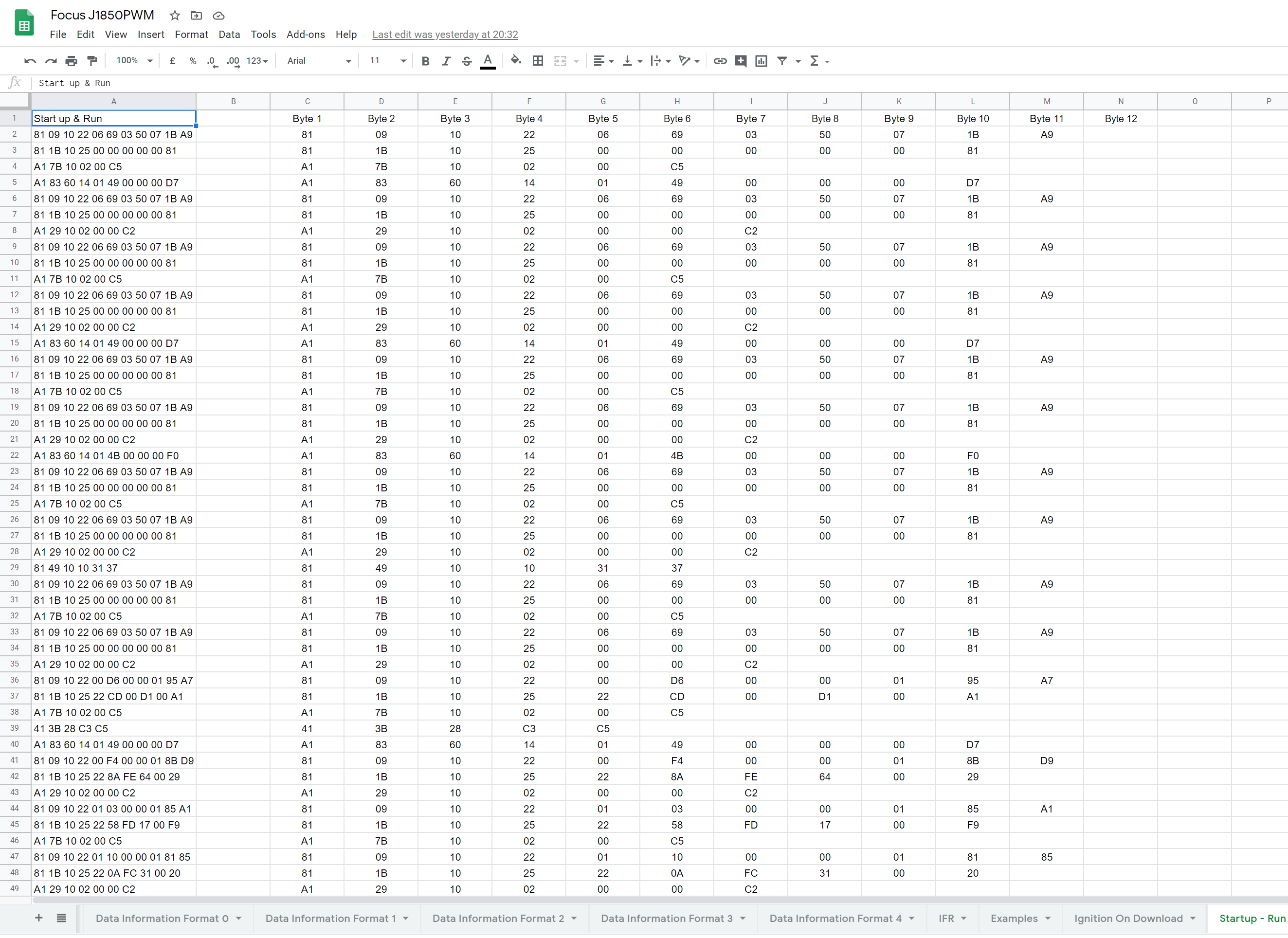
My understanding of the message is the first byte is the priority, then destination, source, up to eight data bytes, and the last is a checksum. Iā€™m sure this address list is correct.

**Control Module ID Number				     				  ID (dec)	ID (hex)**
Body Control Module (BCM)											64	0x40
Inflatable Restraint Sensing and Diagnostic Module (SDM)			88	0x58
Instrument Panel Cluster (IPC)										96	0x60
Head Up Display (HUD)												98	0x62
Radio																128	0x80
Audio Amplifier														129	0x81
CD Changer (CDX)													130	0x82
Digital Radio Receiver (DRR)										137	0x89
Vehicle Communication Interface Module (VCIM)						151	0x97
HVAC Control Module													153	0x99
Driver Door Module (DDM)											160	0xA0
Passenger Door Module (PDM)											161	0xA1
Driver Door Switch (DDS)											164	0xA4
Driver Position Module (DPM)										166	0xA6
Fold Top Controller (FTC)											177	0xB1
Remote Control Door Lock Receiver (RCDLR)							193	0xC1
Steering Column Lock Control Module (SCLCM)							194	0xC2

Steering wheel buttons go to the CD changer, so it decodes them and sends the appropriate packet. For example, when I press the volume down, the changer (0x82) sends a message to 0xA9 with priority 0x91 & payload of 0x90,0x94,0x10 and CRC. The Radio (0x80) sends a message to 94 with a priority of 16 & payload of 0x80 and the explicit volume setting (0-248) & CRC. The amp (0x81) echos the setting (same priority, same payload.) A second press repeats the sequence, but with a low priority (11 instead of 91.)

Some steering wheel functions drive actions in the BCM (like heated steering wheel, adaptive cruise) but the BCM is a bridge between the two busses.

**Emulated by BMC bridged to high speed GMLAN**
Engine Control Module (ECM)						0x11
Transmission Control Module (TCM)				0x18
Distance Sensing Cruise Control Module (DSCC)	0x21
Electronic Brake Control Module (EBCM)			0x28

Here are some points that may help you figure out messages you may not have known needed to exist.

  • In my system, the CD changer is the audio switcher. It routes the head unit, XM, or itself to the amplifier. There has to be some traffic to do that.
  • In my system, the presets for the radio change depending on which driver is detected. That may come from the Driver Position Module?
  • There is a RAP (retained accessory power) feature, When you turn off the car, the radio stays on until the door is opened or it times out.
  • I have a heads-up display that shows the disc information. Someone is telling it that, but I havenā€™t found itā€™s destination address - I stopped looking when I realized there wasnā€™t anything I want to send it.
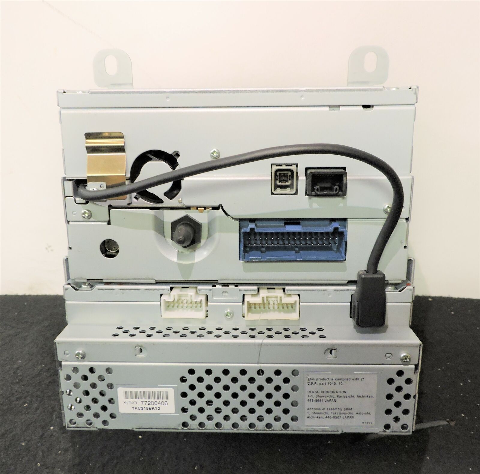
  • On my entertainment combination, there is a cable between the head unit and the cd changer that isnā€™t documented in the vehicle schematics. I went looking for info and found this page. https://www.mictronics.de/projects/cdc-protocols Again, Iā€™d decided not to use the changer, so I stopped digging, but there may be some good clues in there for you.

Hereā€™s a picture of the same model radio and changer. Itā€™s that black cable Iā€™m talking about.


This is starting to get a little long, so Iā€™ll stop here and pull some more things together for another post. Oh, and I should mention that I havenā€™t taken the radio out, nor have I split any of the splice packs to isolate them. Everything Iā€™ve done has been in the car.

Dude! You already solved a problem for me. I had forgotten about priority, and was wondering why I was missing some ā€œnext trackā€ messages. Iā€™m doing exact match on the whole message, and I bet the priority is changing!

Great!

I filter first on ā€œdestination != 255ā€ to completely skip all the heartbeat traffic, then start looking for certain source / destination combinations.

Something else that may matter is, if a module receives a ā€œcritical operating parameter,ā€ it will memorize who sent it and monitor for their heartbeat. If the heartbeat goes missing, it starts using a fail-safe default value. No definition on what defines a critical operating parameter, but I suspect ā€œpriorityā€ may have something to do with it.

I have additional information about the actual commands with J1850 but I need to setup something to store that stuff so it is accessible.

I can add this information to that as well as anything else anyone has gathered. I have the actual GM docs that explain how they work but you guys have pretty much figured most of that stuff out.

I have ranges for modules and I have a tech2 that I hope to use at some point to find diagnostic codes and such to add to it as well.

Rodney

Hi, newbie here. blown away by the work gone into this and had to sign up as I would like some advice on the J1850PWM protocol on my 02 ford focus.

to summarise I have swapped the engine out of my focus and have the new engine running from the donor car (toyota) ECU, so I have removed the standard Ford ECU as its not required anymoreā€¦ however the Ford ECU is connected to the J1850PWM bus network and sends data to various modules, one of which is the instrument cluster which I am most interested in.

Id like to keep the standard instrument cluster but they are mostly useless without specific signals from the Ford ECU (RPM, Speed, coolant temperature, oil pressure, oil temperature, Engine warning light & general warning light), is there a way to replicate those signals based on outputs from the Toyota ECU (for example I have a Coolant temperature signal from the engine) and send them to the instrument cluster in J1850PWM format?

I have the Instrument cluster setup on the bench to test it out i just need to give it the right messages, I also have a few downloaded data dumps from a running focus with the original engine and ECU, I also have access to another focus to download more if required

Help would be seriously appreciated

At this time, as far as I know there is no software to support the PWM interface just yet. I have been sick and dealing with helping my senior mom move to Colorado so I havenā€™t had time to work on this myself. The Hardware supports it, just that there is no software written yet to talk to it.

So you may have to, at least for now, look elsewhere for methods of talking to your setup. Normally you would need to have the device you are trying to hack in a real vehicle working before you could try to mimic it in a lab environment. Unless you get lucky and someone can tell you the codes you need and if you need to wake it up or not.

thanks foe the reply, I understand life comes first, the internet is as always useful up to a point and im greatful for any help available.

I have got a working car with all modules still fitted so i could hack that and read the codes, i do however have some data from another person trying to do something similar, the output looks something like thisā€¦

trying to replicate it on my computer table is proving difficult though

Need to make a new thread for that type of stuff. This thread was more intended on how to get the interfaces and software up and running. Not how to actually get information from your car and figure it out.

Which software is this? Can I get it to work using Savvycan? If not, which software I can use in a windows based OS?

The VPW software is an Arduino script. You would have to build a program to read and write it. I have been too busy to get back to trying to incorporate this into savvy can myself. It is a totally different setup.

Any news regarding J1850 PWM support for M2?

Iā€™ve found that monitoring the protocol is one thing, but actually impersonating a device on the network is something else! For my project, I need some more details on the commands and responses, both generally, and specific to the entertainment system. @redheadedrod: You said you had some actual GM docs on this topic? Can you share those with us? CB.