Support for j1850 VPW/PWM?

You’ve gotta have something wired wrong…

There is nothing special that needs to be done to the bus or wiring…no resistors, etc.

Right now, all I have is my bus analyzer hooked up, and the Arduino Uno with MCZ33990.

When I send a message with the bus analyzer, the Uno displays it to the serial terminal window no problems at all.

Thats literally just with the bus analyzer, and Arduino only. No BCM, no resistors, no ECU’s nothing else on the bus!

Tried it again with nothing more than an ELM327 adapter, and the Arduino.

This is as simple as it gets, as far as setting up/wiring the bus goes.

Works perfectly.

I send a command with the ELM327, Arduino prints it to the terminal window.

I think something is screwed up with the Macchina’s J1850 circuit.

When I upload the extremely simple sketch:

unsigned long duration;
unsigned long timeout;


void setup() {
//  pinMode(DS7_BLUE, OUTPUT);
  pinMode(J1850_VPW_RX, INPUT);
//  pinMode(PS_J1850_9141, OUTPUT);
  SerialUSB.begin(115200);
//  digitalWrite(PS_J1850_9141, LOW);
}

// the loop function runs over and over again forever
void loop() {

    duration = pulseIn(J1850_VPW_RX, HIGH, timeout);    
     if (timeout < 1000){
     if ((duration < 210) && (duration > 190)){
      SerialUSB.println();
      SerialUSB.print("SOF   ");
//      digitalWrite(DS7_BLUE, HIGH);
     }
     
    if (duration < 190){
//      digitalWrite(DS7_BLUE, HIGH);
    SerialUSB.print(duration);
    SerialUSB.print(" ");
    }
     }
//digitalWrite(DS7_BLUE, LOW);
}

It outputs some pulse width times, but its NOT the same as what my Arduino Uno/MCZ33990 outputs.

This sketch is very basic, all it does is measure a HIGH pulse on the VPW line, time how long the pulse is, and print it to the serial window.

It works perfectly on the Arduino Uno/MCZ33990…shows the initial ~200uS start of frame pulse, etc etc.

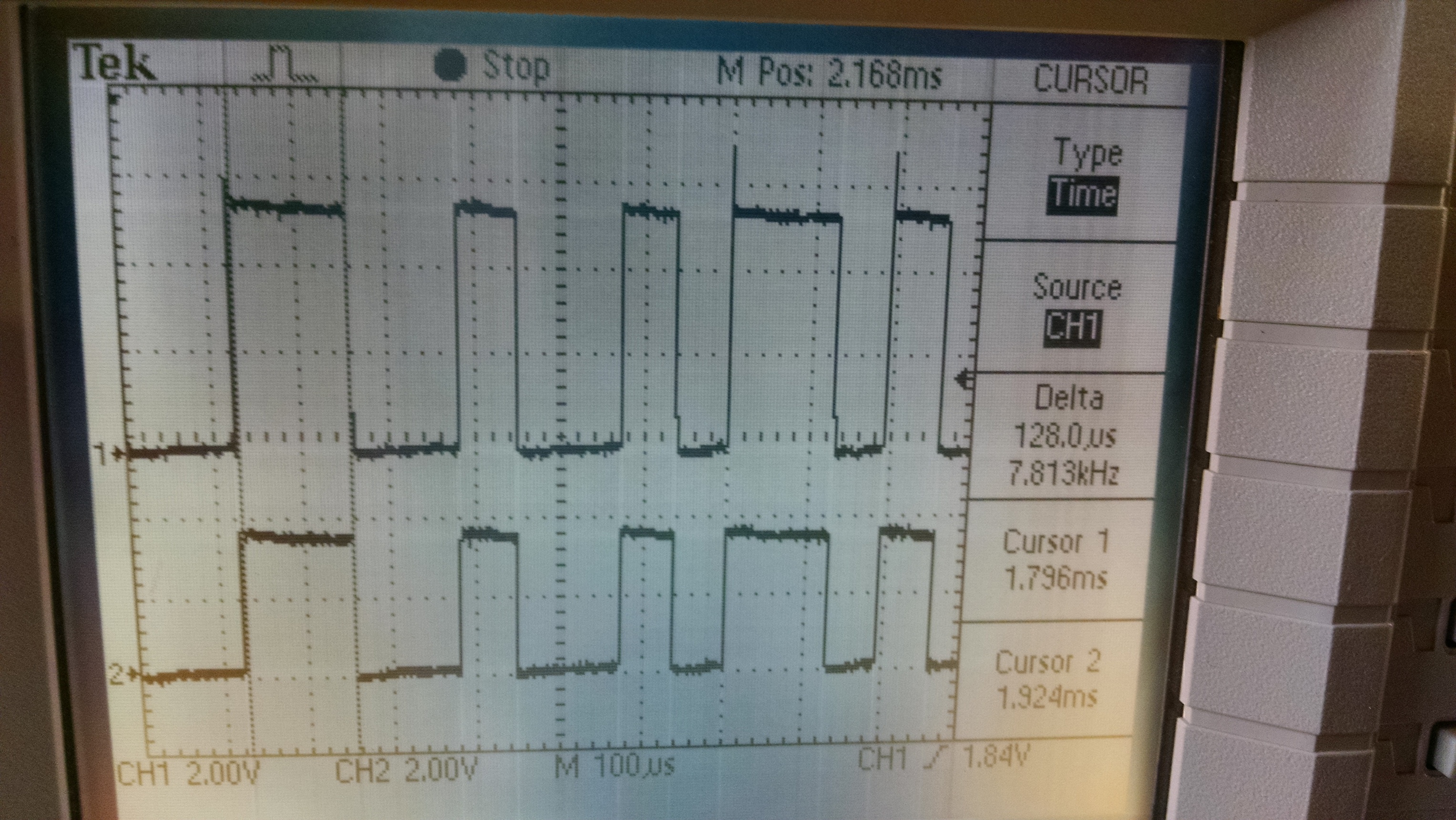
The Macchina, with the same exact sketch loaded, shows random pulse measurements…its not measuring the pulses correctly. Its supposed to show a 200uS start of frame, and then alternate between ~64uS pulses and ~128uS pulses.

Macchina just shows pulses of random lengths.

So its either not measuring things correctly, the serial output is messing up timing, the Macchina “pulseIn” works differently, something is getting blocked…or worst case scenario, the Macchina’s J1850-VPW circuit design is simply just wrong/poor.

Ben

no idea why the forum wont put my code into proper format either??

I clearly put three ` on the beginning and end of the code snippet…doesnt work.

Ben

We just posted some more information on these pins, how they are connected, what they do and that sort of thing:

http://docs.macchina.cc/m2/technical-references/interfaces.html#j1850

Apparently, the three ` characters need to be on their own line before and after the code. I tweaked it for you.

@josh, thank you. That should help.
Just read it and should explain the proper operation.

@dmaxben, will have to get into the documentation a little more and see if there is any trick there…

What I am curious about now is the chip you have says it triggers at below 20% of signal for a low and above 80% of signal for a high. I wonder if the M2 is triggering just at 0% and 100% which might not work. But MAY be adjustable by changing out some resistors perhaps?

How does the Macchina/Due handle “pulseIn” compared to the Uno?

Is the Macchina/Due serial USB slower than the regular old FTDI chip on the Arduino Uno? Could that be messing things up?

In any event, the Macchina isnt even reading the J1850 pulse times correctly…so even at a very basic level, something is broken…whether its the code, or the Macchina’s interface circuit.

This same code works fine on an Arduino Uno and “proper” J1850 transceiver chip.

Can you try storing an array of values big enough to store a whole frame and just display those when the frame is done so you can see what the timings are? That would tell if the serial port is the issue.

I have a hunch it has nothing to do with the Arduino and is just the interface board.

Could always try connecting an Uno to the M2 if you have one of the M2 processor prototype boards that came with the dev kit and try doing it that way? Connect your own pins to the ones on the system. That would tell if it was the Due or the Uno but I am suspecting the edge detection is too tight and needs to be loosened up. While I am not a hardware guy, I would hope that adjusting the resistors may allow adjusting the edge detection to allow a wider range. Just shooting in the dark of course.

OK…well this isnt good.

I have a Due prototype board here…so I hooked up the MCZ33990 chip to the Due prototype board, and uploaded the same sketch.

It reads/measures the pulses CORRECTLY… 64/128uS.

I cant think of any explanation other than theres something seriously wrong with the Macchina’s J1850 VPW circuit/design???

Let’s step back a minute. We took a M2, connected to a emulator and probed the circuit.

Top waveform is Pin 2 of the OBD2 connector. Bottom waveform is “J1850_VPW_RX” signal that goes directly into the processor.

Looks pretty close to me, but we’ll keep investigating.

Any chance you can take a screen grab of a similar setup using the transceiver chip?

My scope (Rigol DS1052) is broken currently…the rotary encoders for the adjustment knobs are all messed up, so its useless.

I think the Due’s serial.print is slow, or messes up/blocks the operation of the processor.

When switching between monitoring the pulses with native USB and programming USB…the readings are different.

Neither readings match the “correct” stuff from the Arduino Uno (direct serial via FTDI/CH340)…but they are different.

So I guess I need to get it to read all the pulses to a cache, then dump the cache to the serial.print window…just to make sure the USB/serial isnt slowing things down.

The real trick is to just get that original sketch working, the one that actually successfully logs J1850 bus traffic on the Uno.

The timer (TIMSK1) stuff is very different on the AVR and ARM processors…so we need to “transpose” that sketch that works on my Arduino Uno into something that’ll work on the Due/Macchina.

I will do what I can to update the program to work with the Due. I will also order some of the chips you are using and hook them up in the next week or so to start working on the driver. If I write a driver for that chip in a Due then the only things that are different are the power on and selector for the M2. When we can resolve what the issue is then it SHOULD work.

This way I can make it so it can work with more than one channel if I so desire so while it will work with M2 if someone wanted to grab a couple and throw them on a Due to do MIM research they can easily.

Rodney

Stupid question/thought…

If I disconnect the processor board of the Macchina, and attach the breakout board…and then tie the “VPW Rx” pin of my Arduino Uno setup to the “VPW Rx” on the Macchina breakout board…shouldnt that theoretically work? To test the VPW circuit of the Macchina.

That would work but first you should fix your sketch… You removed some lines that will bonk the sketch and not make it work.

I suspect you put those lines back in and you may have a different result…

pinMode(PS_J1850_9141, OUTPUT);
pinMode(PWM_nVPW, OUTPUT);
//Turns on power supply to J1850 circuit.
digitalWrite(PS_J1850_9141,LOW);
//Turns on VPW
digitalWrite(PWM_nVPW, LOW);

Those are REQUIRED… Note I think the ,LOW on the last one is missing on my code for some reason…
But try that… Might be the issue all along. Not sure why you commented those lines out.

If I can get a copy of the exact sketch you used and the commands you used from the ELM device I will see if I can duplicate it. I have both a UTH and a UTD M2 and can try it with both.

I have an STN based USB cable which will be slightly different but should act the same.

Rodney

I believe you’ll want to bring PS_J1850_9141 HIGH to bring power to the circuits.

http://docs.macchina.cc/m2/technical-references/pin-mapping.html#power-supplies

Yes you are correct. I changed it on my Github. Again I will try testing this weekend to verify if there is an issue.

I already tried correcting that issue, still doesnt seem to work.

I think we might have to use the “DueTimer” library…?

I think this is the equivalent way to measure pulses/interrupts with high accuracy on the Due.