P1's SWCAN config-pin

Hey,

I have problems configuring SWCAN on P1. I could set up the GPIO in the /boot/uEnv file, and it works. Now I want to set P2_06 and P2_18 pins to HIGH, to listen the SWCAN bus on a GM car.

I tried to configure the pins with the embedded command:
config-pin P2_18 hi
But I got error:
config-pin P2_18 hi ERROR: open() for /sys/devices/platform/ocp/ocp:P2_18_pinmux/state failed, No such file or directory

Basically, I dont have that pinmux file there:
96346876-6d538780-109e-11eb-81aa-553fdff04e6e

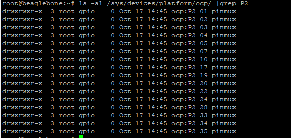
I looked after that GPIO library, thinking maybe that is the problem, but not, it is correctly loaded:
> /opt/scripts/tools/version.sh

    git:/opt/scripts/:[7cdc270818b76d829d247cf05fe309c320a3929a]
    eeprom:[A335PBGL00A21743GPB30299]
    model:[TI_AM335x_PocketBeagle]
    dogtag:[BeagleBoard.org Debian Buster IoT Image 2020-08-25]
    bootloader:[microSD]:[/dev/mmcblk0]:[U-Boot 2019.04-00002-gc9b3922522]:[location: dd MBR]
    UBOOT: Booted Device-Tree:[am335x-pocketbeagle.dts]
    UBOOT: Loaded Overlay:[AM335X-PRU-RPROC-4-19-TI-00A0]
    UBOOT: Loaded Overlay:[BB-ADC-00A0]
    UBOOT: Loaded Overlay:[PB-CAN0-00A0]
    UBOOT: Loaded Overlay:[PB-CAN1-00A0]
    UBOOT: Loaded Overlay:[PB-MCP2515-SPI1]
    kernel:[4.19.94-ti-r50]
    nodejs:[v10.21.0]
    /boot/uEnv.txt Settings:
    uboot_overlay_options:[enable_uboot_overlays=1]
    uboot_overlay_options:[uboot_overlay_addr4=/lib/firmware/PB-CAN0-00A0.dtbo]
    uboot_overlay_options:[uboot_overlay_addr5=/lib/firmware/PB-CAN1-00A0.dtbo]
    uboot_overlay_options:[uboot_overlay_addr6=/lib/firmware/PB-MCP2515-SPI1.dtbo]
    uboot_overlay_options:[uboot_overlay_pru=AM335X-PRU-RPROC-4-19-TI-00A0.dtbo]
    uboot_overlay_options:[enable_uboot_cape_universal=1]
    pkg check: to individually upgrade run: [sudo apt install --only-upgrade <pkg>]
    pkg:[bb-cape-overlays]:[4.14.20200814.0-0~buster+20200814]
    pkg:[bb-wl18xx-firmware]:[1.20200813.1-0~buster+20200813]
    pkg:[kmod]:[26-1]
    pkg:[librobotcontrol]:[1.0.5-git20200715.0-0~buster+20200716]
    pkg:[firmware-ti-connectivity]:[20190717-2rcnee1~buster+20200305]
    groups:[debian : debian adm kmem dialout cdrom floppy audio dip video plugdev users systemd-journal input bluetooth netdev i2c gpio admin spi iio docker tisdk weston-launch xenomai cloud9ide pwm eqep remoteproc]
    cmdline:[console=ttyO0,115200n8 root=/dev/mmcblk0p1 ro rootfstype=ext4 rootwait coherent_pool=1M net.ifnames=0 lpj=1990656 rng_core.default_quality=100 quiet]
    dmesg | grep remote
    [   53.832040] remoteproc remoteproc0: wkup_m3 is available
    [   54.008667] remoteproc remoteproc0: powering up wkup_m3
    [   54.008700] remoteproc remoteproc0: Booting fw image am335x-pm-firmware.elf, size 217168
    [   54.008997] remoteproc remoteproc0: remote processor wkup_m3 is now up
    [   55.838857] remoteproc remoteproc1: 4a334000.pru is available
    [   55.872421] remoteproc remoteproc2: 4a338000.pru is available
    dmesg | grep pru
    [   55.838857] remoteproc remoteproc1: 4a334000.pru is available
    [   55.839046] pru-rproc 4a334000.pru: PRU rproc node pru@4a334000 probed successfully
    [   55.872421] remoteproc remoteproc2: 4a338000.pru is available
    [   55.872630] pru-rproc 4a338000.pru: PRU rproc node pru@4a338000 probed successfully
    dmesg | grep pinctrl-single
    [    0.895597] pinctrl-single 44e10800.pinmux: 142 pins, size 568
    dmesg | grep gpio-of-helper
    [    0.905153] gpio-of-helper ocp:cape-universal: ready
    lsusb
    Bus 002 Device 002: ID 148f:7601 Ralink Technology, Corp. MT7601U Wireless Adapter
    Bus 002 Device 001: ID 1d6b:0002 Linux Foundation 2.0 root hub
    Bus 001 Device 001: ID 1d6b:0002 Linux Foundation 2.0 root hub
    END

I tried to run pinmux-generator, to generate that P2_06 and P2_18 pinmux file, but it throws error:

root@beaglebone:/opt/source/bb.org-overlays/tools/pinmux-generator# ./PocketBeagle.sh
pinmux-4.0.1526-setup.run                                            100%[=====================================================================================================================================================================>]  39.87M  2.91MB/s    in 14s

2020-10-17 15:20:15 (2.76 MB/s) - ‘pinmux-4.0.1526-setup.run’ saved [41810329/41810329]

./lib/pinmux.sh: line 220: ./pinmux-4.0.1526-setup.run: cannot execute binary file: Exec format error
cp: cannot stat 'tmp/pinmux/deviceData/AM335x/AM335x.json': No such file or directory
##################
P1_02
cat: AM335x.json: No such file or directory

Tried to install pinmux manually, but it doesnt support armhf architecture.

Already contacted Macchina support about this, but no answer yet.
No documents available at the moment about setting up SWCAN.
What am I doing wrong?

Hello, I worked on the setup for the PocketBeagle P1 cape, so this is something I can help to figure out.

The reason that P2_06 and P2_18 pinmux state files are not available (/sys/devices/platform/ocp/ocp:P2_18_pinmux/state) is because the PB-MCP2515-SPI1.dts overlay disables it:

This is okay as the overlay sets the pinmux to GPIO output mode:

This means the state of the pins can be controlled (HIGH or LOW) by writing to value (1 or 0) to the corresponding file in /sys/class/gpio

From the PocketBeagle reference, we can see that P2.06 is GPIO 57 and P2.18 is GPIO 47.

These commands should set the pins high:

sudo su
cd /sys/class/gpio
echo 47 > export
cd gpio47
echo 1 > value
cd ..
echo 57 > export
cd gpio57
echo 1 > value

Yup, I ran into the same small speed bump myself.

To be clear, the DTB does not disable the GPIO, it disables the ability to configure what kind of GPIO it is - it forces it to be an output only, which means that you only need /sys/class/gpio as stated previously and don’t need to do anything with pinmux.

Yep, this is how I finally managed to make it work yesterday. So the only problem was that because of the overlay, it keeps resetting after reboot, so I have to find a workaround for that.
Thanks btw :slight_smile:

Thank you everyone, especially @fustini!

@Entropy512 - thank you for the offer to post up your Python script.

What would be the best longer-term solution to make this easier for the next person?

OK, I can’t directly upload the Python scripts, so I’ll try to paste them here:

First, this sets up CAN for a Bolt EV. I MAY have the 250k for CAN1 wrong for a Bolt, I’m not sure as it’s been a while.

#!/bin/sh
/sbin/ip link set can0 down
/sbin/ip link set can1 down
/sbin/ip link set can2 down

/sbin/ip link set can0 up type can bitrate 500000
/sbin/ip link set can1 up type can bitrate 250000
/sbin/ip link set can2 up type can bitrate 33333

Now, here’s a Python script that uses Adafruit BBIO ( https://pypi.org/project/Adafruit-BBIO/ ) to set up the PHY in normal mode:

#!/usr/bin/env python

import Adafruit_BBIO.GPIO as GPIO

GPIO.setup("P2_6", GPIO.OUT)
GPIO.setup("P2_18", GPIO.OUT)
GPIO.output("P2_6", GPIO.HIGH)
GPIO.output("P2_18", GPIO.HIGH)

The GPIO.setup lines may not actually be needed.

This attempts to precondition a Volt/Bolt (Warning: In attempting to flail against the Bolt’s firewall, aka SDGM in service manuals, I may have broken it. It’s fairly close, there are examples I’ll dig up later of someone who preconditioned an older Volt using a Macchina M2… It will not work on a Bolt because the OBD port is on the wrong side of the SDGM. My own projects are on hold until I figure out a good way to tap into the “dirty” buses on the other side of the SDGM - likely at the radio if I can find the right connector housings.)

#!/usr/bin/env python3

import Adafruit_BBIO.GPIO as GPIO
import time
import can

GPIO.setup("P2_6", GPIO.OUT)
GPIO.setup("P2_18", GPIO.OUT)
#Mode0 low and Mode1 high = HS wakeup
GPIO.output("P2_6", GPIO.LOW)
GPIO.output("P2_18", GPIO.HIGH)

bus = can.interface.Bus(channel='can2', bustype='socketcan')

bus.send(can.Message(arbitration_id=0x101, data=[0xfe, 0x01, 0x3e, 0x00, 0x00, 0x00, 0x00, 0x00], is_extended_id=False))
time.sleep(0.1)
bus.send(can.Message(arbitration_id=0x100, data=[], is_extended_id=False))
time.sleep(0.1)
bus.send(can.Message(arbitration_id=0x62d, data=[0x01, 0x40, 0x00, 0x00, 0x00, 0x00, 0x00, 0x00], is_extended_id=False))
time.sleep(0.5)
bus.send(can.Message(arbitration_id=0x101, data=[0xfd, 0x02, 0x10, 0x04, 0x00, 0x00, 0x00, 0x00], is_extended_id=False))
time.sleep(0.1)
bus.send(can.Message(arbitration_id=0x621, data=[0x01, 0x40, 0x00, 0x00, 0x00, 0x00, 0x00, 0x00], is_extended_id=False))
time.sleep(0.1)
bus.send(can.Message(arbitration_id=0x7ec, data=[0x01, 0x50, 0xaa, 0xaa, 0xaa, 0xaa, 0xaa, 0xaa], is_extended_id=False))

time.sleep(0.2)
GPIO.output("P2_6", GPIO.HIGH)
bus.send(can.Message(arbitration_id=0x1024e097, data=[0x00, 0x00, 0xff], is_extended_id=True))
time.sleep(0.2)
bus.send(can.Message(arbitration_id=0x1024e097, data=[0x80, 0x01, 0xff], is_extended_id=True))
time.sleep(0.2)
bus.send(can.Message(arbitration_id=0x1024e097, data=[0x00, 0x00, 0xff], is_extended_id=True))
time.sleep(0.2)
bus.send(can.Message(arbitration_id=0x1024e097, data=[0x00, 0x01, 0xff], is_extended_id=True))
time.sleep(0.2)
bus.send(can.Message(arbitration_id=0x1024e097, data=[0x00, 0x00, 0xff], is_extended_id=True))

I’ll try to dig up more links/info later and figure out a good way to update the official documentation.