Help out a noob - Hyundai Excel '97

Hey everyone,

I received my Macchina just a few days ago and have been excited to put some of my ideas into practice.

I’ve actually not really done much microprocessor stuff before (I’m a web dev - feel free to judge) so bare with me if I ask any dumb questions :slight_smile:

I’ve successfully managed to turn on and off LEDs on the board thanks to modifying example code, which was a fun 15 minutes or so, but I am struggling to make the leap from that to actually using input from my car to do things.

What I would really like to do as a first project is read the RPM from my car, and light up LEDs on the Macchina based on that.

I have a Hyundai Excel '97 model, and based on the pinout of the OBD connector (pins 1,2,4,5,8,9,10,11 are populated) + lots of googling I’ve figured out that the protocol is likely J1850 PWM. Picture here; http://ibb.co/gSCMmR

With some googling I’ve managed to find some code;
https://www.macchina.cc/guide/m2/automotive-interfaces/j1850-pwm
and this too

So with that I (think) I can turn on the J1850 chip and set it to PWM mode. But that’s where I get stuck - how do I read a specific code/message on the bus?

I’ve found this library, but it’s a bit advanced for me - does anyone have any examples of how I might use it? (or if it’s even a good idea to use it?)

Thanks for any help or insight you can give! When I get good at this I’m hoping to do a Back To The Future style time travel dashboard with lots of seven segment displays :wink:

Please read the threads already discussing this. The hardware supports it but the software portion has not been written yet.

The Pin out you have is wrong. It’'s 1,4,5,7,8,14,15,16.

http://docs.macchina.cc/m2/technical-references/installation.html

so one swcan and k-line/lin.

not the j1850 protocol.

That’s, good I guess, those protocols seem to be better supported. Does that mean I can use either protocol?

I’m confused though, why is every pinout image of the OBD connector the opposite of the one on that Macchina page? For example the pins are backwards on this image http://www.mbcluster.com/Old_Website/Media_Diagnostics/ODBII%20Master%20Pinout.jpg

Shouldn’t they match? Or am I missing something fundamental here

Getting the protocol right is probably an important step :slight_smile:

Depends on if your looking at the plug or the socket… Plug is the car side normally, and plug is M2 or dongle side…

Current firmware only supports CANBUS and SWCAN. There have been some talking that a lin/kline library exists but not included in M2RET firmware as far as I know at this time.

Rodney

Ah, I see! My mistake

So based on that I tried both the Single-Wire CAN (MCP2515) library and the OBD9141 library found on this page
http://showcase.macchina.cc/libraries.html

But it turns out I think I’ve broken the OBD port in my car, since the M2 isn’t even lighting up anymore when I connect it to the OBD port and have the car on and have the Blink example sketch loaded (this used to work). The port was incredibly tight the first few times I tried it, and on my last unplug yesterday I must have damaged a wire or something - so I’ll need to somehow get behind the dash and see what’s going on.

I’ll probably also buy a cheap scantool and give that a go to make sure it’s the OBD port that is broken and not my M2 or code. Hopefully that will also confirm the protocol as well…

Thanks for your help guys, I’ll keep this thread updated on my progress as I go

Just a quick note to mention I just tested the OBD9141 library you mentioned and also found here:

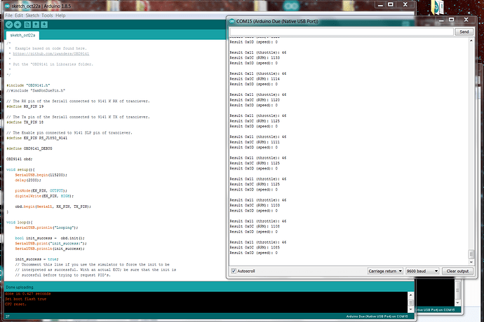
Wasn’t able to get it to work via new M2 board definitions just yet, but was able to make it work using the “SamNonDuePin.h” library + selecting "Arduino Due Native USB. Here is GIST with lines that make sure transceiver is awake and powered. We’ll figure out what needs to be tweaked to the code to make this run under the “Macchina M2” board selection next.

And here is terminal output showing what a 2004 Toyota Rav 4 looks like idling in the driveway:

Let us know if you get this to work and if you figure out what happened to your OBD2 port!

Please note that with the latest firmware the blue light does not come on when the M2 is powered up. It flashes for a very brief moment then goes out. (Might be a good idea to turn it back on so we know the unit is powered up and running.)

You can connect your M2 to savvycan if you have the default firmware loaded and it should connect to the hardware and recognize 2 buses on it.

Hey guys! My cheap scantool from eBay finally arrived (several days late) and it’s now the weekend so I’ve been able to run some tests.

Unfortunately, it seems like my OBD port is broken somehow. With ignition on, I get power to the port, but the scantool doesn’t make a data connection at all (scan tool has 3 lights, 1 for power, 1 for OBD, 1 for PC. Only the power light seems to come on)

Using a multimeter, I determined that pins 16 (voltage) 4 (signal ground) and 5 (chassis ground) are all fine, so it must be one of the others. Looking at the pins and the wires behind the connector, they all seem fine.

At a bit of a loss at the moment, have lost some enthusiasm with all these OBD problems (I just want to code!) and it’s not trivial to get the OBD harness out in my car…

Might take another look at it next weekend

Check your fuses. You likely have one blown. One of the ignition or BCM or something similar.

Checked all fuses, all completely fine…